Urea hydrolytic and pyrolytic compound ammonia preparation system for denitration in thermal power plant

A technology of urea hydrolysis and thermal power plant, which is applied in the field of ammonia production system, can solve the problems of increased energy consumption, corrosion of product pipelines, agglomeration of furnace impurities, etc., and achieve the effect of avoiding whole-process heat tracing, avoiding blockage of pipelines, and reducing energy consumption

Pending Publication Date: 2017-09-22
XIAN THERMAL POWER RES INST CO LTD
View PDF5 Cites 3 Cited by
  • Summary
  • Abstract
  • Description
  • Claims
  • Application Information

AI Technical Summary

Problems solved by technology

[0007] Compared with the two processes, urea hydrolysis has the advantage of low energy consumption (low reaction temperature), but the product pipeline has the risk of corrosion and clogging, and requires full heat tracing, which increases energy consumption; urea pyrolysis has rapid response, and the pipeline does not need heat preservation , no pipeline blockage, etc., but the cost of the pyrolysis furnace is high, and additional fuel will be consumed to reach the reaction temperature. After a long time of use, impurities will agglomerate in the lower part of the furnace, which will affect the stability of use.

Method used


Image

  • Urea hydrolytic and pyrolytic compound ammonia preparation system for denitration in thermal power plant

Examples


Embodiment Construction

[0023] The present invention is described in further detail below in conjunction with accompanying drawing:

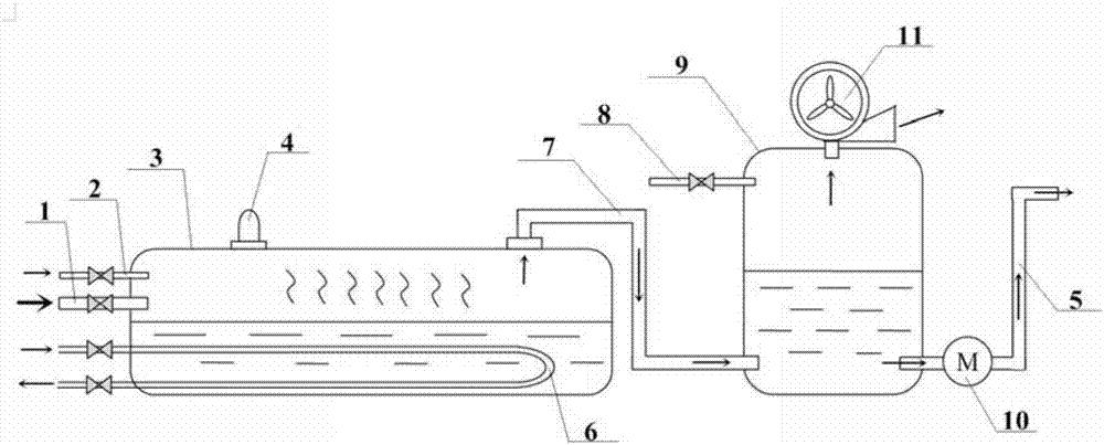
[0024] refer to figure 1 , the urea hydrolysis pyrolysis composite ammonia production system for denitrification in a thermal power plant according to the present invention comprises a urea solution inlet pipe 1, a hydrolysis reactor 3, a carbon removal tank 9, a demineralized water pipe 8 and an exhaust fan 11; a urea solution inlet pipe 1 Be communicated with the inlet of hydrolysis reactor 3 sides, the bottom of hydrolysis reactor 3 is provided with the steam heater 6 that is used for heating the urea solution in the hydrolysis reactor 3, the top outlet of hydrolysis reactor 3 and the carbon removal tank 9 The bottom inlet is connected, the desalted water inlet on the side of the carbon removal tank 9 is connected to the desalinated water pipe 8, the exhaust fan 11 is located at the top opening of the carbon removal tank 9, and the ammonia water pipe 5 is connected ...


PUM


Abstract

The invention discloses a urea hydrolytic and pyrolytic compound ammonia preparation system for the denitration in a thermal power plant. The urea hydrolytic and pyrolytic compound ammonia preparation system comprises a urea solution inlet pipe, a hydrolytic reactor, a decarbonization tank, a desalted water pipe and an exhaust fan, wherein the urea solution inlet pipe is communicated with an inlet in the side surface of the hydrolytic reactor; the bottom of the hydrolytic reactor is provided with a steam heater for heating a urea solution in the hydrolytic reactor; a top outlet of the hydrolytic reactor is communicated with a bottom inlet of the decarbonization tank; a desalted water inlet in the side surface of the decarbonization tank is communicated with the desalted water pipe; the exhaust fan is located at a top opening of the decarbonization tank; a bottom outlet of the decarbonization tank is communicated with an ammonia water pipe. The system is low in energy consumption; a product cannot block a pipeline; moreover, the cost is low.

Description

technical field [0001] The invention relates to an ammonia production system, in particular to a urea hydrolysis pyrolysis composite ammonia production system for denitrification in a thermal power plant. Background technique [0002] The flue gas emitted by coal-fired power plants contains a large amount of nitrogen oxides and needs to be purified. At present, the flue gas denitrification technology widely used is based on ammonia (NH 3 ) as a reducing agent, reducing NOx to non-toxic and harmless nitrogen (N 2 ). For safety considerations, the preparation of ammonia in thermal power plants is based on urea (CO(NH 2 ) 2 ) as raw materials, divided into two technical routes of low-temperature hydrolysis and high-temperature pyrolysis. The urea solution undergoes a hydrolysis reaction below 200°C, and the reaction equation is: [0003] NH 2 CONH 2 +(1+X)H 2 O→2NH 3 ↑+CO 2 ↑+(X)H 2 O↑ [0004] In practical engineering applications, the product gas only contains 28...

Claims


Application Information

Patent Timeline
Patent Type & Authority Applications(China)
IPC IPC(8): C01C1/08
CPCC01C1/086
Inventor 王林刘爱军郭三虎张亚夫刘超王红雨
Owner XIAN THERMAL POWER RES INST CO LTD
Why Eureka
Try Eureka