
Deflection-swinging type semi-automatic rod replacing hydraulic rock drilling machine

A rock drilling rig, semi-automatic technology, applied in drill pipe, drill pipe, earthwork drilling and other directions, can solve the problems of large vibration, endanger personal safety, high production cost, achieve simple and reasonable structure, reduce safety hazards, and low manufacturing cost Effect

Inactive Publication Date: 2014-12-10
GUILIN HUALI HEAVY INDS
View PDF7 Cites 11 Cited by
  • Summary
  • Abstract
  • Description
  • Claims
  • Application Information

AI Technical Summary

Problems solved by technology

The structure is very complex, the requirements for the hydraulic control system and the electric control system are very high, the manufacturing precision is high, the manufacturing and maintenance costs are high, and the working conditions of the drilling rig are harsh, the vibration is large, and the reliability of the rod changing mechanism is poor.
[0006] (2) The drill arm of the existing hydraulic rock drilling rig usually does not have a yaw structure, and can only swing back and forth, and cannot yaw left and right
When the drilling rig stops on the horizontal slope and drills holes, the verticality of the drill pipe and the surface cannot be guaranteed, resulting in the phenomenon of drilling inclined holes; sometimes it is even impossible to drill due to the influence of the working terrain
In order to achieve yaw, some need to be equipped with a special yaw beam and connected to the drill boom. The yaw beam itself has a complex structure and a large size, which increases the mass of the machine, the grounding pressure of the whole machine is large, the use is limited, and the production cost high
At the same time, the connecting pin shaft is prone to wear and tear due to the large force, causing the drill arm to fall off, causing serious losses and even endangering personal safety.

Method used


Image

  • Deflection-swinging type semi-automatic rod replacing hydraulic rock drilling machine
  • Deflection-swinging type semi-automatic rod replacing hydraulic rock drilling machine
  • Deflection-swinging type semi-automatic rod replacing hydraulic rock drilling machine

Examples


Embodiment Construction

[0039] The principles and features of the present invention will be described below with reference to the accompanying drawings. The examples cited are only used to explain the present invention, and are not used to limit the scope of the present invention.

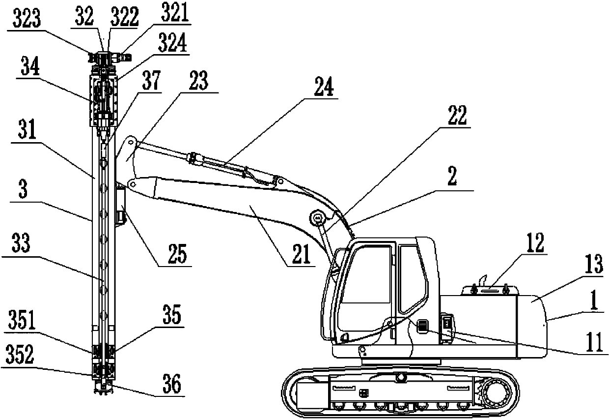
[0040] Such as Figure 1 to Figure 6 As shown, a deflection type semi-automatic rod-changing hydraulic rock drilling rig includes a carrier machine 1, a boom 2 and a drilling machine 3. One end of the boom 2 is placed on the upper end of the carrier machine 1, and the boom 2 The other end of is connected to the middle of the drill 3, and the boom 2 drives the drill 3 to deflect;

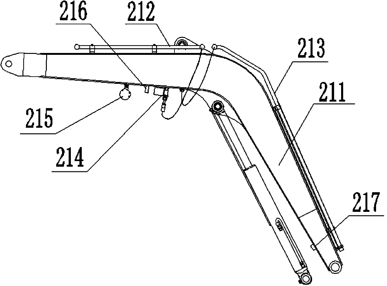
[0041] The boom 2 includes a boom body 21, a boom cylinder 22, a turntable 23, a boom cylinder 24, and a yaw cylinder 25. One end of the boom body 21 is connected to the carrier machine 1, and the boom cylinder One end of 22 is also connected to the carrier machine 1, the other end of the boom cylinder 22 is connected to the bend of the boom body 21...


PUM


Abstract

The invention relates to a deflection-swinging type semi-automatic rod replacing hydraulic rock drilling machine. The machine comprises a carrier machine, a movable arm and a drilling machine body. One end of the movable arm is arranged at the upper end of the carrier machine, and the other end of the movable arm is connected with the middle of the drilling machine body. The movable arm drives the drilling machine body to swing in a deflected mode. Compared with the prior art, drill rod replacing is convenient, potential safety hazards are reduced, the directions for deflection swinging of the drilling machine are increased, and drilling precision is improved.

Description

Technical field [0001] The invention relates to the technical field of engineering machinery, in particular to a tilting type semi-automatic rod changing hydraulic rock drill. Background technique [0002] The current hydraulic rock drilling rigs mainly have the following problems: [0003] (1) Existing hydraulic rock drilling rigs have two ways to change rods, one is full manual rod changing, and the other is fully automatic rod changing. [0004] Full manual rod replacement is the complete use of manual unloading and connecting rods. It usually requires 2 to 3 people to cooperate to complete it. When the drill rod is manually jammed for disassembly, it is easy to slip due to insufficient clamping force, and it is difficult to unload the rod. Cause personal injury, high risk factor, laborious manual operation, high labor intensity, and low work efficiency. [0005] Fully automatic rod changing usually includes a series of devices such as upper manipulator, lower manipulator, upper r...

Claims


Application Information

Patent Timeline
IPC IPC(8): E21B7/02E21B15/00E21B19/18E21B21/16E21B19/084
Inventor 周夏南陈宗宜周洪同王琦
Owner GUILIN HUALI HEAVY INDS
Learn More