Later-compression-stroke carbon filling type carbon powder engine

A compression stroke and engine technology, applied in the direction of powdered engine fuel, engine components, combustion engines, etc., can solve the problems of high piston temperature, consumption of lubricating oil, concentration reduction, etc., to achieve strong output power, low exhaustion speed, and short production cycle short effect

Inactive Publication Date: 2014-12-10
李松
View PDF0 Cites 2 Cited by
  • Summary
  • Abstract
  • Description
  • Claims
  • Application Information

AI Technical Summary

Problems solved by technology

This reduces the concentration of carbon powder in the mixture, thereby reducing the success rate of ignition
At the same time, because the carbon powder adheres to the piston, most of the heat released after being ignited will be directly transmitted to the piston, resulting in excessive temperature of the piston and easier damage
At the same time, only a small amount of energy is transferred to the air after the carbon powder adhering to the piston burns, resulting in insufficient heating of the air, resulting in a decrease in engine output torque
[0006] 2. During the process of the piston compressing the carbon-air mixture, due to the lubricating oil on the cylinder wall, part of the carbon powder adheres to the cylinder wall, and the result is similar to that described in the previous defect: the success rate of ignition is reduced , so that the engine output torque decreases
Moreover, the carbon powder burned on the cylinder wall will consume a large amount of lubricating oil; the non-burned carbon powder on the cylinder wall will seriously hinder the reciprocating motion of the piston.
[0007] 3. The low success rate of ignition leads to unstable output torque of the engine, and may even cause a dead fire
Even if the ignition of the next cycle is successful, the excess carbon powder will promote the reaction C+CO 2 = The occurrence of 2CO, the reaction is an endothermic reaction, which reduces the gas temperature, thereby reducing the output torque of the engine, or in other words, making the output torque difficult to control

Method used


Image

  • Later-compression-stroke carbon filling type carbon powder engine
  • Later-compression-stroke carbon filling type carbon powder engine
  • Later-compression-stroke carbon filling type carbon powder engine

Examples


Embodiment Construction

[0030] The specific implementation mode of the present invention is illustrated below by way of example.

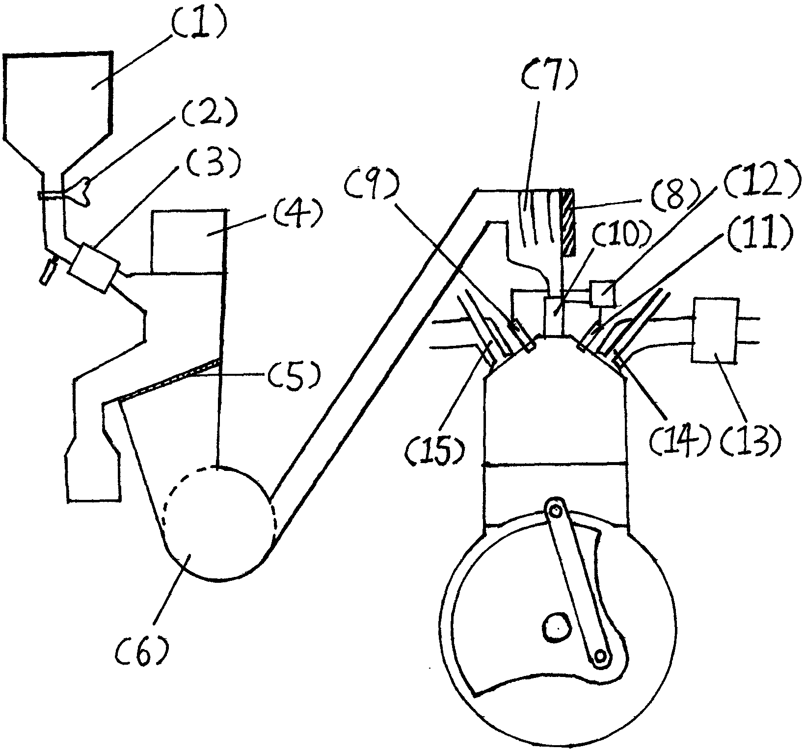
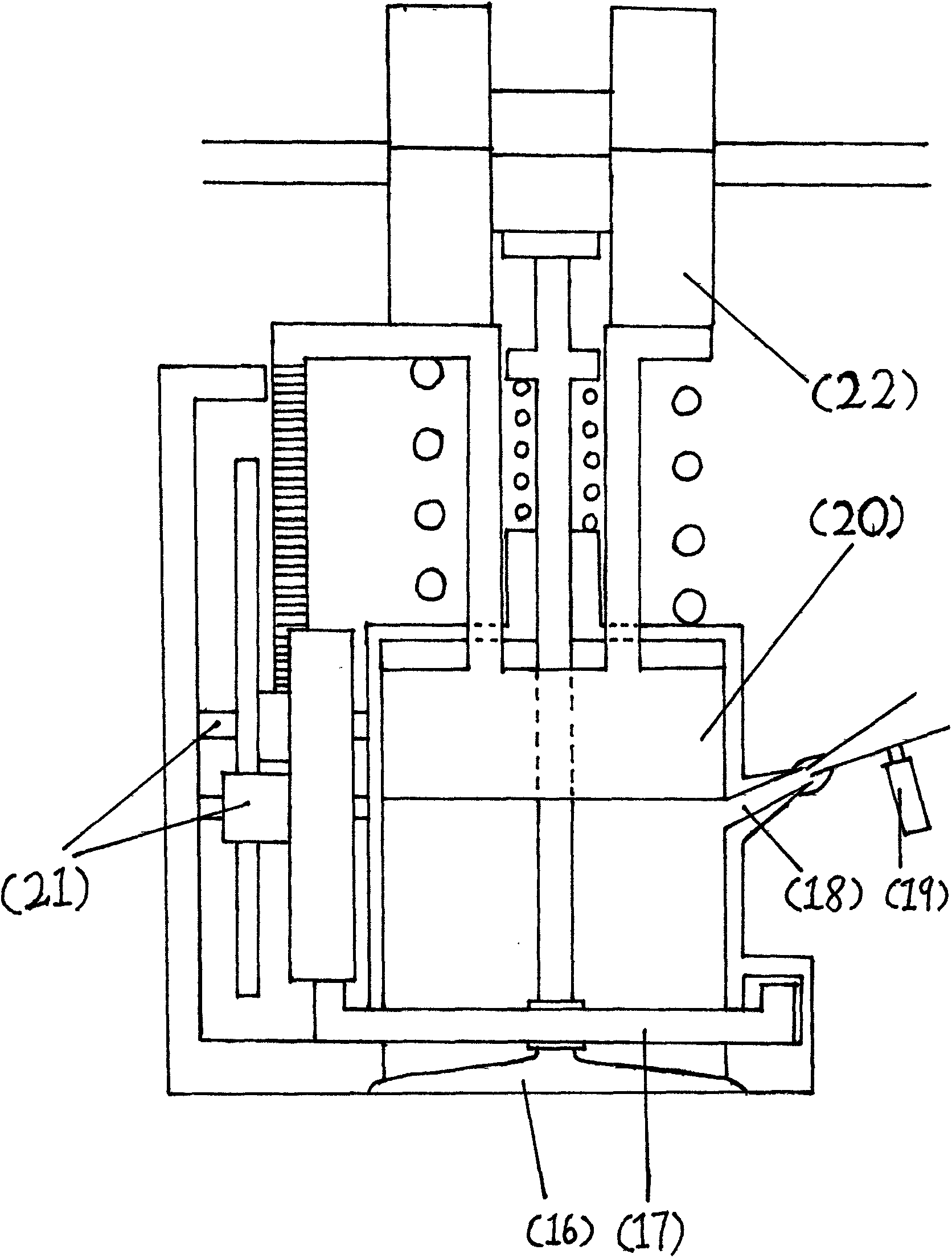
[0031] The first is an ignition-type compression stroke late carbon-charged toner engine. The toner leaks from the powder storage tank (1) to the electric dryer (3), and then falls to the filter screen (5), where (4) is an exhaust fan + air filter, responsible for sucking in air to assist the toner filter. Powder extractor (6) extracts the carbon powder to the top of the engine main body. Then the carbon powder enters the carbon charging device.

[0032] The engine is a four-stroke engine. When the compression stroke ends and the piston moves to the top dead center, the carbon filling device is filled with carbon powder, and then ignited by the spark plug, the carbon-air mixture burns violently, and the high-pressure expansion pushes the piston to do work. Among them, there is a ring of high temperature and high pressure resistant lubricating oil material at the top de...


PUM

PropertyMeasurementUnit
radiusaaaaaaaaaa
radiusaaaaaaaaaa

Abstract

The invention discloses a later-compression-stroke carbon filling type carbon powder engine, and belongs to the field of internal combustion engines. The engine has a spark ignition type and a compression ignition type. Petroleum resources are exhausted day by day, and therefore it is imperative that renewable resources are utilized for replacing petroleum to become new energy sources. It is a feasible idea that carbon powder is utilized for solving the problem. It is a pity that many defects still exist in the carbon powder engine in the aspect of the internal combustion engines, for example, the combustion rate is low, power output is unstable, and carbon powder blocks piston motion, and the problems are urgently needed to be solved. Various problems of the carbon powder engine are solved by changing the carbon filling mode, a combustion chamber, the ignition mode and the like of the carbon powder engine. The engine can be used as a device capable of converting chemical energy of carbon into mechanical energy and can be used for power generation of the carbon powder internal combustion engines, an automotive carbon powder engine and the like.

Description

technical field [0001] The invention relates to a solid-gas internal combustion engine, a mechanical device for converting the chemical energy of carbon powder and oxygen into mechanical energy. Background technique [0002] The current mainstream engines are gasoline engines and diesel engines. These two engines have superior performance and are indeed great inventions in human history. However, since the source of diesel oil and gasoline is oil, and oil resources are decreasing day by day, the price of fuel oil has risen, which has increased the operating costs of the two internal combustion engines. At the same time, it is an inevitable fact that oil resources will eventually be exhausted. The currently proven oil can only be exploited by human beings for 40 years. It can be seen that gasoline and diesel engines will inevitably withdraw from the stage of history in the near future. [0003] Another possible engine uses ethanol as fuel. However, the current method of pr...

Claims


Application Information

Patent Timeline
Patent Type & Authority Applications(China)
IPC IPC(8): F02B45/02
CPCY02T10/30
Inventor 李松
Owner 李松
Why Eureka
Try Eureka