A solid fuel clean combustion device and combustion method

A combustion device and solid fuel technology, which are applied to the combustion of solid fuel, combustion method, combustion chamber, etc., can solve the problems of inability to achieve balanced combustion of volatile matter and fixed carbon, and inability to achieve clean combustion of solid fuel.

Active Publication Date: 2016-07-06
卓卫民
View PDF8 Cites 0 Cited by
  • Summary
  • Abstract
  • Description
  • Claims
  • Application Information

AI Technical Summary

Problems solved by technology

[0008] The problem to be solved by the present invention is that the prior art cannot realize the balanced combustion of volatile matter and fixed carbon in the fuel during the combustion process, especially in the charging link, so that the clean combustion of the solid fuel cannot be realized, and then ideal combustion theory and balanced combustion technology Propose a solid fuel clean combustion device for balanced combustion of solid fuel volatile matter and fixed carbon, and a combustion method for the solid fuel clean combustion device

Method used


Image

  • A solid fuel clean combustion device and combustion method
  • A solid fuel clean combustion device and combustion method
  • A solid fuel clean combustion device and combustion method

Examples


Embodiment 1

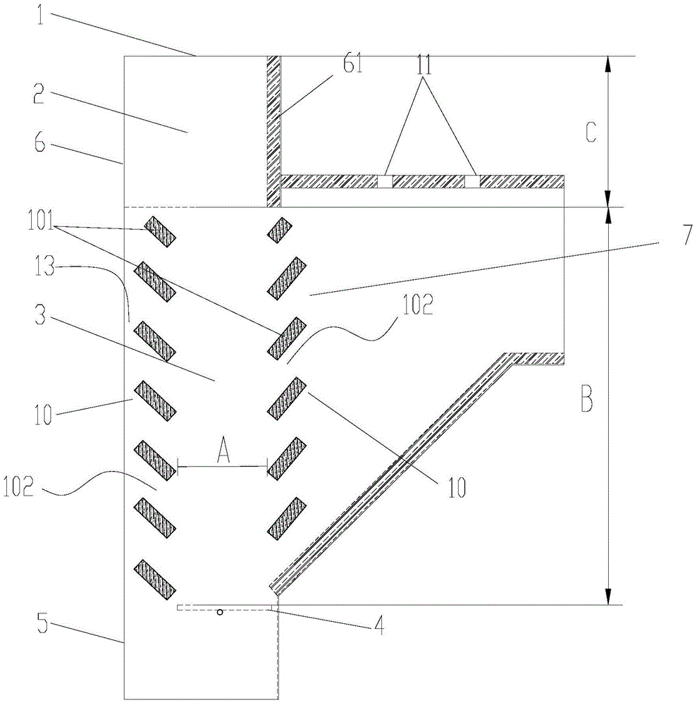
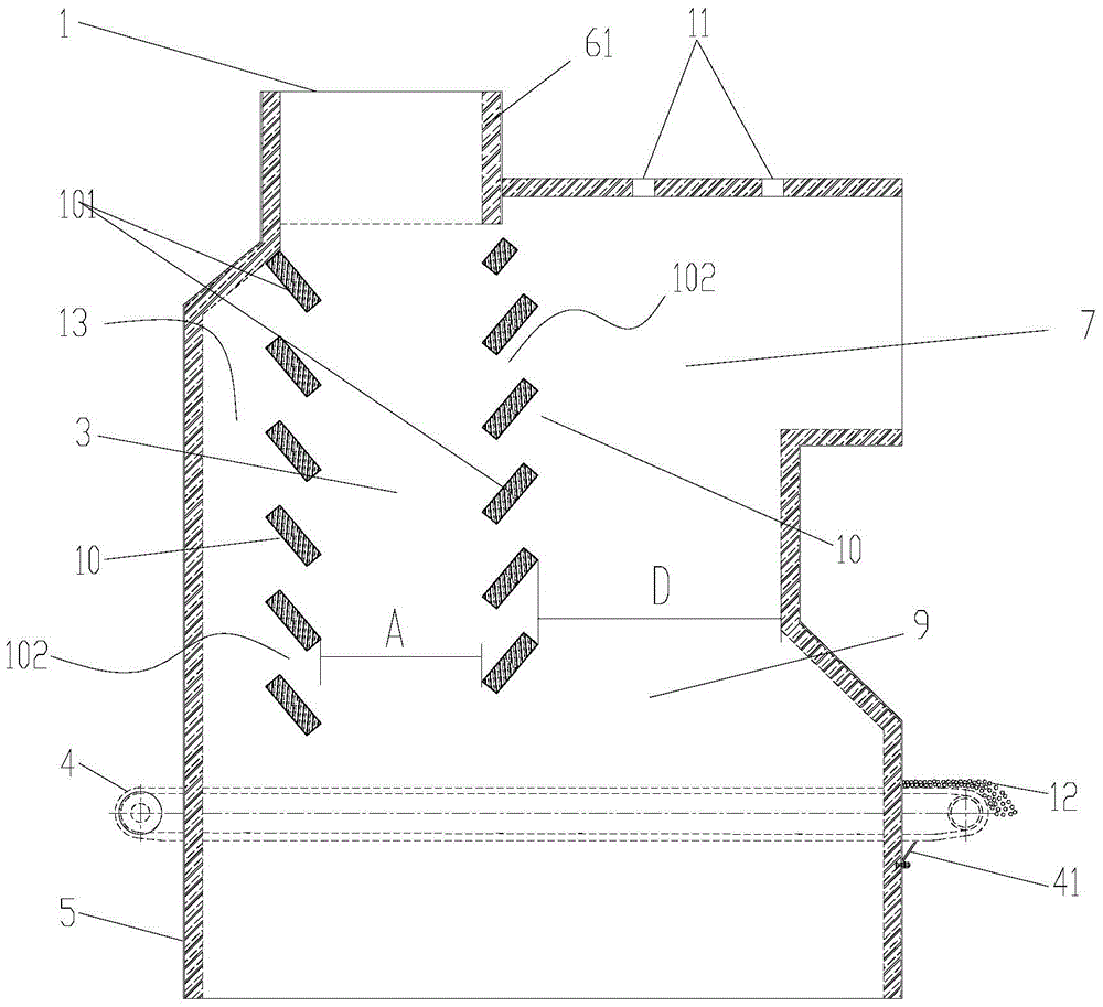
[0055] like figure 1 As shown, the solid fuel clean combustion device of this embodiment includes a furnace body 6, an upper air inlet 1 is arranged on the upper part or the top of the furnace body 6, and a lower air inlet 5 is arranged on the lower part or the bottom. A furnace cavity is arranged inside. In this embodiment, the upper air inlet 1 is arranged at the top of the furnace body 6 , and the lower air inlet 5 is arranged at the lower part of the furnace body 6 . The fire outlet 7 is arranged on one side of the furnace body 6. In this embodiment, the fire outlet 7 is preferably arranged on the right side of the furnace body 6, and the setting position of the fire outlet 7 is lower than the The above air inlet 1 and the height of the fire outlet 7 are within the conventional selection range in this field. In this embodiment, the height of the fire outlet 7 is not less than 200mm. The positional relationship between the lower air inlet 5 and the fire outlet 7 can be se...

Embodiment 2

[0074] This embodiment provides a clean combustion device for solid fuel, which is different from Embodiment 1 in that: in this embodiment, the ventilation fins of the ventilation wall 10 are composed of several vertically connected ventilation fins; or The ventilation wall 10 is composed of several vertically arranged ventilation fins or baffle plates, and several of the ventilation fins or baffle plates are located on the same longitudinal plane, and the distance between the top of each of the ventilation fins or baffle plates is at the distance between its adjacent The bottom end of the upper ventilation sheet or the baffle has a gap suitable for ventilation and capable of blocking the leakage of solid fuel.

Embodiment 3

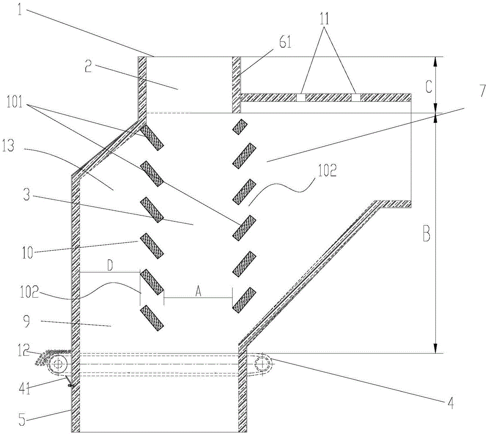
[0076] This embodiment provides a clean combustion device for solid fuel, which is different from Embodiment 1 in that: at least one of the two ventilation walls is inclined, so that the combustion zone 3 is formed to be large at the top and small at the bottom or small at the top Under large burning space.

[0077] Specifically, in the present embodiment, the two ventilation walls 10 are arranged obliquely, and the direction of inclination of the ventilation walls is inclined downward from the outside to the inside, so that the combustion zone 3 is formed to be large at the top and small at the bottom. inverted trapezoid.

[0078] Still further, the inclined ventilating wall 10 is composed of several fixed fire grates 101 arranged at intervals in the longitudinal direction, and the fixed fire grates 101 are arranged inclined and downward toward the interior of the combustion zone 3, so that the solid fuel is discharged from the upper air inlet. 1. When entering the combustio...


PUM


Abstract

The invention discloses a solid fuel clean combustion device and a solid fuel clean combustion method. In a furnace cavity, two ventilation walls are longitudinally opposed to the air outlet; Combustion area placed and burned, above the main combustion chamber is a backup combustion area connected to the upper air inlet and suitable for placing solid fuels, the grate is located at the bottom of the combustion area, the height of the combustion area is not less than 200mm, and the width of the combustion area is not less than 200mm , the height of the pre-combustion zone shall not be less than 150mm. Through the above settings, the pre-combustion area and the combustion area have reasonable structural dimensions, and the two areas have spatial stability. In the combustion area, it can be ensured that the generation of volatiles is a stable and slow process, so that the volatiles and fixed carbon Always burn according to the ratio of the two in the fuel, so as to achieve a balanced combustion of the volatile matter and fixed carbon in the solid fuel, and avoid the generation of black smoke in the flue gas.

Description

technical field [0001] The invention relates to a solid fuel clean combustion device and a solid fuel clean combustion method, belonging to the technical field of solid fuel combustion. Background technique [0002] At present, smog has become a disastrous weather in many parts of China, which has attracted the attention of the whole society. In 2014, China proposed at the national level the requirements to strictly control the PM2.5 index and prevent smog pollution through "decompression of coal combustion, strict control of vehicles, adjustment of industries, strengthening of management, joint prevention and control, and governance by law". Therefore, haze control and haze prevention has become an important project in China's social and environmental governance. [0003] The formation of smog is the result of the interaction between specific climatic conditions and human activities; with the vigorous development of human economic and social activities, the concentration o...

Claims


Application Information

Patent Timeline
Patent Type & Authority Patents(China)
IPC IPC(8): F23B10/02F23B50/00F23L9/02F23M9/00
Inventor 卓卫民刘浩吴涛杨进成卓宇轩王昕
Owner 卓卫民
Why Eureka
Try Eureka