Laser seaborne tide gauge and tide gauging method thereof

A tide measuring and laser technology, which is applied to tide measuring instruments and the field of tide measuring, can solve the problems of large changes in water level acquisition accuracy, decreased water level acquisition accuracy, fatigue of pressure metal work, etc., and achieves remarkable application effect, no maintenance, high performance Safe and reliable effect

Inactive Publication Date: 2014-12-10
交通运输部北海航海保障中心天津海事测绘中心
View PDF5 Cites 2 Cited by
  • Summary
  • Abstract
  • Description
  • Claims
  • Application Information

AI Technical Summary

Problems solved by technology

[0004] Pressure type: use a pressure sensor to collect the pressure change caused by the change of seawater tide level. It is necessary to put the pressure sensor into the water several meters to obtain the change of pressure data; the connection is relatively simple, but it works for a long time. The work fatigue of the pressure metal can easily cause the accuracy of water level collection to drop; the maintenance is more frequent, and the sensor needs to be replaced regularly
[0005] Float type: in which the water float and the weight are connected to the turntable through a steel wire, and the tide level change of the seawater is driven by the change of the turntable to collect the change data of the seawater tide level. This method takes a long time to use and the technology is relatively mature, but the equipment is relatively heavy. Complicated installation and frequent maintenance
[0006] Ultrasonic type: It detects the change of sea tide level by emitting ultrasonic waves through ultrasonic sensors. The water level acquisition equipment is relatively simple, easy to install, and has no contact with seawater; however, ultrasonic sensors are easily affected by changes in the coastal environment, and the accuracy of water level acquisition varies greatly and is stable. Poor performance, seawater tide level detection has been seldom used at present

Method used


Image

  • Laser seaborne tide gauge and tide gauging method thereof
  • Laser seaborne tide gauge and tide gauging method thereof
  • Laser seaborne tide gauge and tide gauging method thereof

Examples


Embodiment Construction

[0047] Below in conjunction with the accompanying drawings and preferred embodiments, the specific implementation, structure and features provided by the present invention are described in detail as follows:

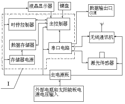
[0048] like figure 2 , Figure 4-Figure 8As shown, a laser sea tide gauge, the instrument includes a wireless communication machine, a laser sensor, a keyboard, a display, a main board circuit and a main power board; all parts except the laser sensor are arranged in a sealed case; the sealed case passes through three The sealed plugs are respectively connected to the external battery input line, wireless communication machine antenna, laser sensor 232 serial port and power line; the laser sensor is also watertight, and a waterproof socket is the data output port (COM).

[0049] figure 2 Mainboard circuit 1 shown in the dotted line frame in the middle is made up of master controller, clock controller, data memory, memory power supply, serial port circuit and periphera...


PUM


Abstract

The invention relates to a laser seaborne tide gauge and a tide gauging method thereof. The gauge comprises a wireless communicator, a laser sensor, a keyboard, a displayer, a mainboard circuit and a main power supply board, wherein the mainboard circuit is formed by connecting a main controller, a clock controller, a data storage device, a storage device power supply, a serial circuit and a peripheral supporting circuit; the main controller is connected with the keyboard, the displayer, the clock controller, the data storage device and the serial circuit, and the data storage device is connected with the storage device power supply; the serial circuit is connected with a data output port, the wireless communicator and the laser sensor; the main power supply board is used for supplying power supplies for the circuits and equipment, and an external storage battery and a solar panel are used for supply voltage input or an alternating-current power grid is used for supplying a power supply through AC-DC for the main power supply board. The laser seaborne tide gauge obtains change of tide level data through change of laser, and the tide gauging method is simple, high in gauging precision and wide in range. The gauge is easy and convenient to mount, is basically maintenance-free and is stable and reliable in performance.

Description

technical field [0001] The invention relates to a tide gauge and a tide gauge method thereof, in particular to a laser sea tide gauge and a tide gauge method thereof. Background technique [0002] The tide gauge is an instrument for observing the fluctuation of ocean tides. The tide gauges installed in various tide gauge stations in the sea area collect the tide level data of the corresponding sea area for hydrological monitoring and management. [0003] At present, tide gauge measurement technology has the following forms: [0004] Pressure type: use a pressure sensor to collect the pressure change caused by the change of seawater tide level. It is necessary to put the pressure sensor into the water several meters to obtain the change of pressure data; the connection is relatively simple, but it works for a long time. The working fatigue of the pressure metal can easily cause the accuracy of water level collection to drop; the maintenance is more frequent, and the sensor n...

Claims


Application Information

Patent Timeline
Patent Type & Authority Applications(China)
IPC IPC(8): G01C13/00G08C17/02
CPCG01C13/004
Inventor 杨习成汪连贺白婷颖刘雷肖鸿飞曲萌边志刚
Owner 交通运输部北海航海保障中心天津海事测绘中心
Why Eureka
Try Eureka