Oscillating temperature sensor using rf radio frequency signal as energy

A temperature sensor and radio frequency signal technology, applied in the field of sensors, can solve the problems of short working distance and inconvenient use of sensors, and achieve the effect of long working distance, increased working distance and accurate reading

Active Publication Date: 2016-11-02
CETC CHIPS TECH GRP CO LTD
View PDF9 Cites 0 Cited by
  • Summary
  • Abstract
  • Description
  • Claims
  • Application Information

AI Technical Summary

Problems solved by technology

However, the sensor still has the following problems to be solved: the working distance of the sensor is short (less than 3 meters), so that the reader must be used within a certain distance from the sensor head, which is inconvenient to use

Method used


Image

  • Oscillating temperature sensor using rf radio frequency signal as energy

Examples


Embodiment

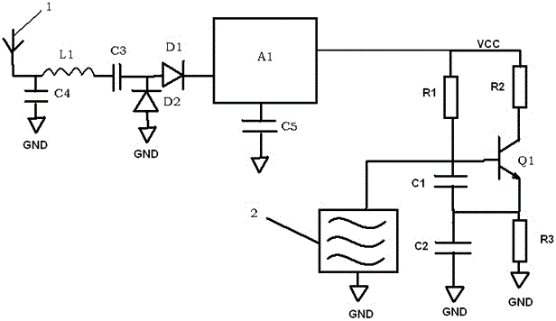
[0020] Oscillating temperature sensors powered by RF signals, such as figure 1 As shown, it includes an antenna 1, an energy collection module and a sensor head; the antenna 1 is used to receive radio frequency signals; the energy collection module includes a matching circuit, a first diode D1 and a power management circuit; the matching circuit includes a matching inductor L1 and The matching capacitor C4 is connected in parallel with the feed point end of the antenna 1, and the matching inductor L1 is connected in series between the feed point end of the antenna 1 and the anode of the first diode D1; the power management circuit includes a DC / DC boost chip A1 With the energy storage capacitor C5, the input end of the DC / DC boost chip A1 is connected to the cathode of the first diode D1, and the load voltage output end of the DC / DC boost chip A1 is connected to the live wire of the oscillating temperature sensor , the energy storage voltage output end of the DC / DC booster chi...


PUM

PropertyMeasurementUnit
Sensitivityaaaaaaaaaa

Abstract

The oscillating temperature sensor with RF radio frequency signal as energy provided by the present invention includes an antenna, an energy collection module and a sensor head; the energy collection module includes a matching circuit, a first diode and a power management circuit; the matching circuit and the second A diode connection; the power management circuit includes a DC / DC boost chip and an energy storage capacitor, the input terminal of the DC / DC boost chip is connected to the cathode of the first diode, and the load voltage output of the DC / DC boost chip The end is connected to the fire wire of the oscillating temperature sensor, and the energy storage voltage output end is connected to the ground wire of the oscillating temperature sensor through the energy storage capacitor; the sensor head includes an acoustic surface resonator and a triode. The SAW oscillator is formed by combining the SAW resonator and the triode, which can transmit the return signal with greater power, increasing the working distance and data transmission time of the sensor. The reader can read the data of the sensor at a long distance and is easy to use.

Description

technical field [0001] The invention belongs to the field of sensors, in particular to an oscillating temperature sensor. Background technique [0002] Equipment such as power switch cabinets, transformers, and high-voltage transmission lines play an important role in the high-voltage power transmission industry. However, after long-term use of these devices, aging phenomena such as rust will occur, which affects the conductivity of metal conductors, increases conductor resistance, and generates heat under high voltage conditions. During the peak power supply in summer, the high temperature can cause fires and even explosions. In order to solve this problem, the best way is to install a temperature sensor at the position where there is a metal conductor inside the device, monitor the temperature change in real time, and cut off the power supply in case of abnormal temperature. [0003] However, the installation of sensors inside high-voltage equipment is limited by several...

Claims


Application Information

Patent Timeline
Patent Type & Authority Patents(China)
IPC IPC(8): G01K11/22
Inventor 肖立龙峥陈婷婷
Owner CETC CHIPS TECH GRP CO LTD
Why Eureka
Try Eureka