Design method of wireless power transmission device

A technology of wireless power transmission and design method, which is applied in the direction of circuit devices, electrical components, electromagnetic wave systems, etc., and can solve problems such as coil position sensitivity

Active Publication Date: 2014-12-10
INST OF ELECTRICAL ENG CHINESE ACAD OF SCI
View PDF5 Cites 12 Cited by
  • Summary
  • Abstract
  • Description
  • Claims
  • Application Information

AI Technical Summary

Problems solved by technology

The invention can solve the problem that the wireless power transmission device is sensitive to the position of the coil, avoid complicated coil alignment operations, reduce the complexity of the system structure, save design costs, and improve the convenience of use of the wireless power transmission device

Method used


Image

  • Design method of wireless power transmission device
  • Design method of wireless power transmission device
  • Design method of wireless power transmission device

Examples


Embodiment Construction

[0036] The present invention will be further described below in conjunction with the accompanying drawings and specific embodiments.

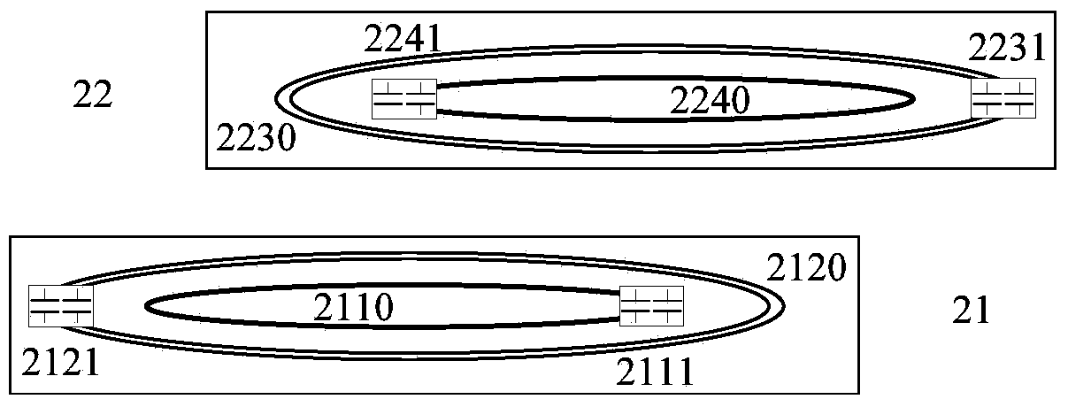
[0037] The structure diagram of a typical four-coil wireless power transmission device is as follows: figure 2 As shown, the wireless power transmission device includes a transmitting coil 2110, an amplifying coil at the transmitting end 2120, an amplifying coil at the receiving end 2230, and a receiving coil 2240, a total of four coils, as well as corresponding transmitting coil resonance compensation capacitors 2111 and transmitting end amplifying coil resonance compensation capacitors. 2121, the receiving end amplifying coil resonance compensation capacitor 2231 and the receiving coil resonance compensation capacitor 2241, a total of four compensation capacitors. The transmitting coil, the amplifying coil at the transmitting end and its compensation capacitor constitute the transmitting device 21 ; the amplifying coil at the receiving end, ...


PUM


Abstract

A design method of a wireless power transmission device includes: step A, under the condition that a receiving device and a transmitting device are aligned completely, measuring intrinsic electric parameters of each coil of the wireless power transmission device and measuring mutual inductance of each two coils to record as a coupled matrix M0; step B, under the condition that the receiving device deflects to a maximum designed deflection value relative to the transmitting device, remeasuring the intrinsic electric parameters of each coil of the wireless power transmission device and remeasuring mutual inductance of each two coils to record as a coupled matrix M1; step C, under the condition that the receiving device and the transmitting device are aligned completely, setting up a nonlinear programming optimization model by taking a maximum efficiency and an assigned power as objective functions, and working out an optimal capacitance value Copt0 of a resonance compensation capacitor by iteration; step D, in consideration of influences of deflection of relative positions of the receiving device and the transmitting device, optimizing the target functions to set up a new nonlinear programming model, and solving the optimization problem by taking the Copt0 as an initial value for iteration to obtain a final capacitance value Copt1 of the resonance compensation capacitor.

Description

technical field [0001] The invention relates to a design method of a wireless power transmission device. Background technique [0002] Since the magnetic resonance wireless power transmission technology was proposed by the Massachusetts Institute of Technology (MIT) in 2007, because of its advantages in transmission distance, it has broad market prospects in military industry, consumer electronics, life medicine, electric vehicles and other industries. Various related products have been developed one after another. An inherent feature of the wireless power transmission system is that the transmitted power and transmission efficiency will be greatly reduced when the transceiver coil is offset. According to the existing technology such as patent CN 203014500U, the wireless power transmission system designed by patent CN 103208866A, only when the wireless power transmission The desired output power and efficiency can only be achieved when the transmitter and receiver of the sy...

Claims


Application Information

Patent Timeline
IPC IPC(8): H02J17/00H02J50/10
Inventor 王丽芳朱庆伟廖承林郭彦杰李芳
Owner INST OF ELECTRICAL ENG CHINESE ACAD OF SCI
Why Eureka
Try Eureka