Carotid artery and femoral artery cannula capable of reducing ischemic time of brain or limbs and application thereof

A technology for carotid and femoral arteries, applied in carotid and femoral artery cannulation and application fields, can solve difficult to achieve blood flow distribution and pressure regulation, easily damaged axillary artery, subclavian vein, right common carotid artery ischemia, etc. problems, to achieve the effect of reducing limb ischemia time, shortening operation time, and light blood damage

Inactive Publication Date: 2014-12-17
黄强
View PDF8 Cites 0 Cited by
  • Summary
  • Abstract
  • Description
  • Claims
  • Application Information

AI Technical Summary

Problems solved by technology

[0003] The existing technology usually uses a straight intubation tube with a length of 20 cm, one end of which is connected to the artificial heart-lung machine arterial perfusion tube, and the other end is inserted into the right axillary artery. Because the right axillary artery is located deep, it is difficult to expose and intubate, and it is easy to damage the axillary artery. Arteries, subclavian veins, axillary nerves, etc., the operation is more difficult
Moreover, during the operation, the patient’s right upper limb at the distal end was always in an ischemic state due to the intubation facing the proximal end; an artificial blood vessel with a diameter of 8 mm was used, one end was connected to the arterial perfusion tube of the artificial heart-lung machine, and the other end had to be sutured to the right axillary artery Or the right common carotid artery, and it takes 10 minutes or more to suture the artificial blood vessel, which may lead to ischemia of the right common carotid artery, which may cause irreversible ischemic brain damage in some patients
The disadvantage of the suture method can also lead to blood leakage from the anastomosis during heparinization; in addition, the arterial perfusion of different parts must use their own proprietary straight cannula or artificial blood vessel, which cannot be used universally. Inability or difficulty with cannulation for blood flow distribution and pressure regulation as needed

Method used


Image

  • Carotid artery and femoral artery cannula capable of reducing ischemic time of brain or limbs and application thereof
  • Carotid artery and femoral artery cannula capable of reducing ischemic time of brain or limbs and application thereof
  • Carotid artery and femoral artery cannula capable of reducing ischemic time of brain or limbs and application thereof

Examples


Embodiment 1

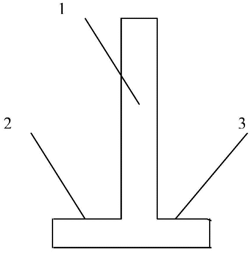
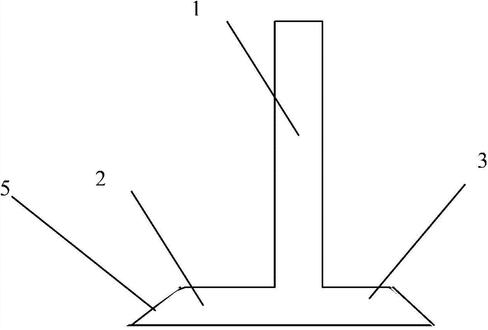
[0040] Such as figure 1 , the simplest structure of the present invention includes the cannula main body 1 at the blood supply end, which is characterized in that it also includes two branch short tubes with shunt and partial pressure that communicate with the cannula main body 1—the proximal end tube 2 and the The distal end tube 3 is a medical perfusion plastic tube with a T-shaped structure on the overall structure. The internal diameters are all taken as 8mm, and the ends of the above-mentioned proximal end tube 2 and distal end tube 3 form a 45° oblique opening 5 to facilitate intubation.

[0041] Usually, the length of the main body of the cannula is 20 cm, and the proximal end tube 2 and the distal end tube 3 are 1.5 cm and 1.0 cm, respectively.

Embodiment 2

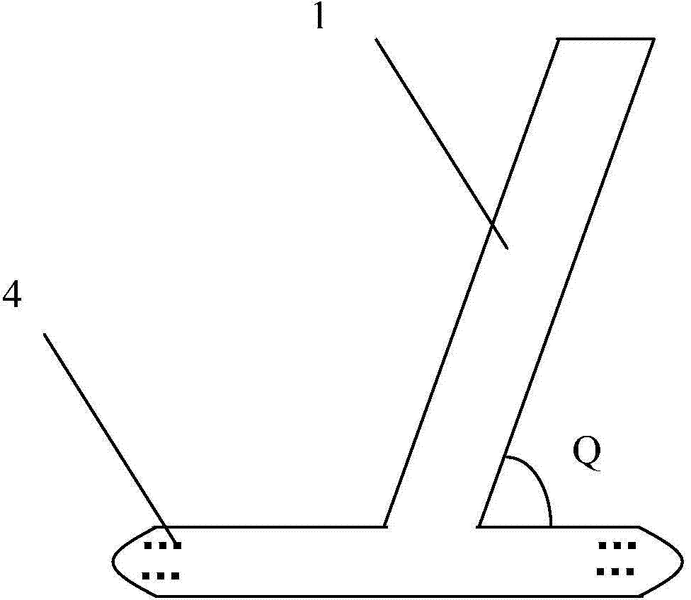
[0043] Such as Figure 4 , the present invention includes a cannula main body 1 at the blood supply end, which is characterized in that it also includes a proximal end tube 2 and a distal end tube 3 communicating with the cannula main body 1, and the three are medical plastics with a Y-shaped structure on the same plane tube, and the proximal tube 2 and the cannula main body 1 at the blood supply end form an angle of 120°, that is, Q is an angle of 60° to reduce blood flow resistance and pump pressure, thereby ensuring perfusion flow and reducing blood damage.

Embodiment 3

[0045] Such as image 3 , the present invention includes a cannula main body 1 at the blood supply end, which is characterized in that it also includes two branch tubes that communicate with the cannula main body 1 and have a shunt and a partial pressure effect—a proximal end tube 2 and a distal end tube 3, forming The perfusion plastic tube for medical extracorporeal circulation with a T-shaped or Y-shaped structure in the overall structure, and the above-mentioned perfused plastic tube with a T-shaped or Y-shaped structure in the overall structure, its proximal end tube 2 and distal end tube The ends of 3 can be spherical crowns with side holes, and there are 6 symmetrically arranged side holes, and it is ensured that the total area of ​​each side hole is greater than the maximum opening area of ​​the intubation tube main body 1.


PUM

PropertyMeasurementUnit
Lengthaaaaaaaaaa
The inside diameter ofaaaaaaaaaa

Abstract

The invention relates to a carotid artery and femoral artery cannula capable of reducing ischemic time of a brain or limbs and application thereof. The carotid artery and femoral artery cannula comprises a cannula body with a blood supplying end, and is characterized by also comprising a proximal artery tube and a distal artery tube which communicate with the cannula body and play roles in shunting and sharing pressure, thus forming an extracorporeal circulation plastic perfusion tube of which the whole structure is T-shaped or Y-shaped, wherein an included angle is reserved between the proximal artery tube of the perfusion tube with Y-shaped structure and the cannula body of the blood supplying end to distribute and adjust blood flow volume of perfusion. The carotid artery and femoral artery cannula is applied to a right common carotid artery to achieve systemic arterial perfusion during the extracorporeal circulation period and selective cerebral perfusion during deep hypothermic circulatory arrest, and also applied to the femoral artery to achieve systemic arterial perfusion during the extracorporeal circulation period and meanwhile avoid lower limb ischemia. Obviously, the carotid artery and femoral artery cannula is convenient to operate, strong in universality and greatly shortened in operation time, so that ischemic time of the brain or the limbs can be greatly reduced, and success rate of aortic arch surgery is improved, and thereby carotid artery and femoral artery cannula can be widely used.

Description

[0001] technology field. [0002] The invention relates to the field of medical devices, in particular to a carotid artery and femoral artery cannula capable of reducing brain or limb ischemia time and its application. Background technique [0003] The existing technology usually uses a straight intubation tube with a length of 20 cm, one end of which is connected to the artificial heart-lung machine arterial perfusion tube, and the other end is inserted into the right axillary artery. Because the right axillary artery is located deep, it is difficult to expose and intubate, and it is easy to damage the axillary artery. Arteries, subclavian veins, and axillary nerves are more difficult to operate. Moreover, during the operation, the patient’s right upper limb at the distal end was always in an ischemic state due to the intubation facing the proximal end; an artificial blood vessel with a diameter of 8 mm was used, one end was connected to the arterial perfusion tube of the art...

Claims


Application Information

Patent Timeline
IPC IPC(8): A61M25/14
Inventor 黄强黄晓朱蕾
Owner 黄强
Why Eureka
Try Eureka