Inoculant particle screening equipment

A technology for screening equipment and inoculants, which is applied in the field of inoculant particle screening equipment, can solve problems such as high cost, low production efficiency, and failure to achieve inoculation effects, and achieve a high degree of automation and increase work efficiency.

Inactive Publication Date: 2014-12-17
成都宏源铸造材料有限公司
View PDF6 Cites 3 Cited by
  • Summary
  • Abstract
  • Description
  • Claims
  • Application Information

AI Technical Summary

Problems solved by technology

[0003] The inoculant is an additive that can promote the formation of graphite, reduce the tendency of whitening, improve the morphology and distribution of graphite, increase the number of eutectic groups, and refine the matrix structure. It is currently the most widely used 75 ferrosilicon inoculant; in the casting process , the molten iron in the ladle has a high temperature of about 1400 degrees Celsius. If there is powder in the inoculant, it will be oxidized and burned on the surface during the process of adding molten iron, and the inoculation effect cannot be achieved. Usually, the inoculant products are all particles with a particle size of 0.2mm or more. The particle size below 0.2mm is the dust loss. The more dust is generated, the greater the loss and the higher the cost. In the traditional inoculant production process, there will inevitably be powder, which is mainly transported and screened manually in the later stage of screening and bagging. The production efficiency is very low. During the transfer of inoculant particles, the scattered inoculant particles are often not well recycled. It will take a certain amount of time to manually collect them.

Method used


Image

  • Inoculant particle screening equipment
  • Inoculant particle screening equipment
  • Inoculant particle screening equipment

Examples


Embodiment Construction

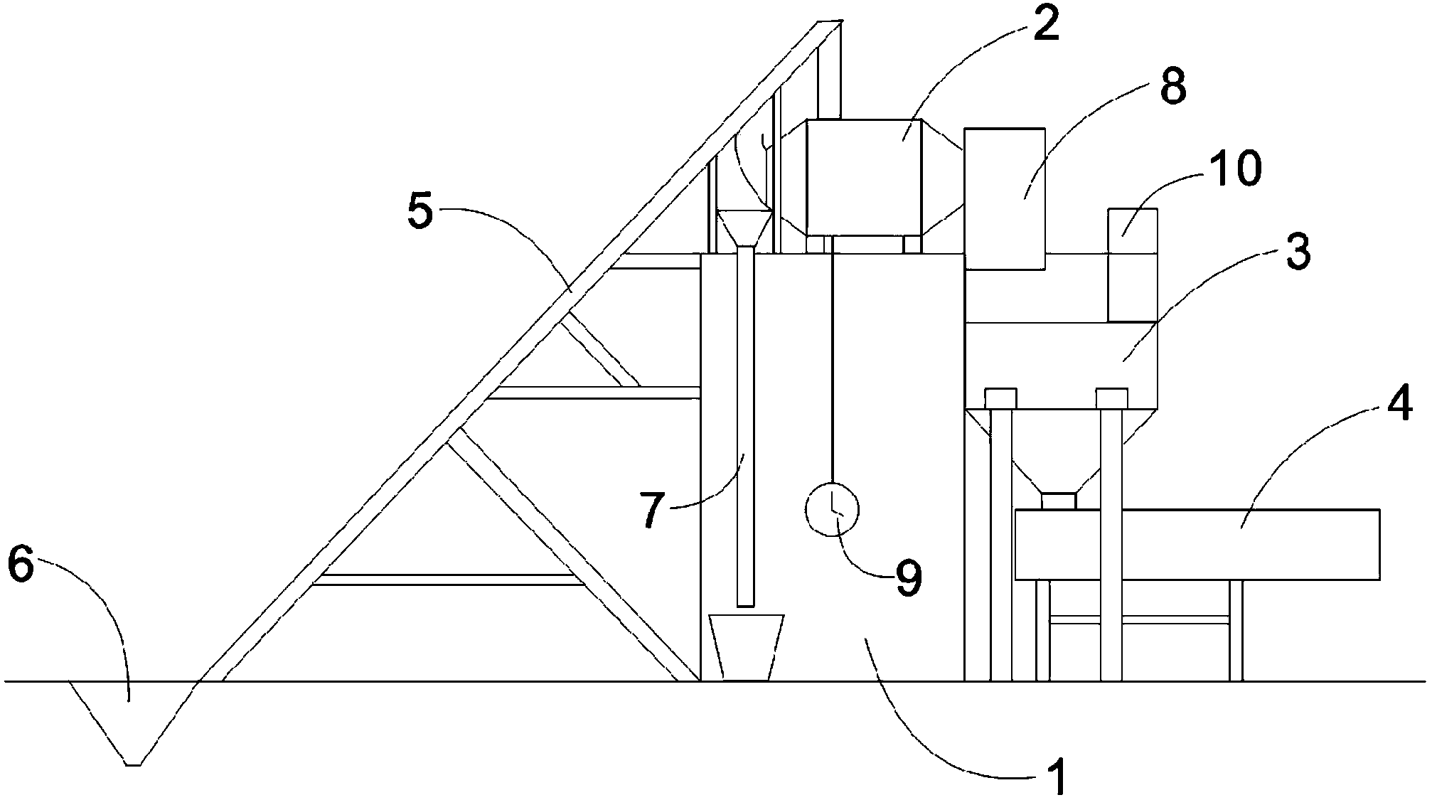
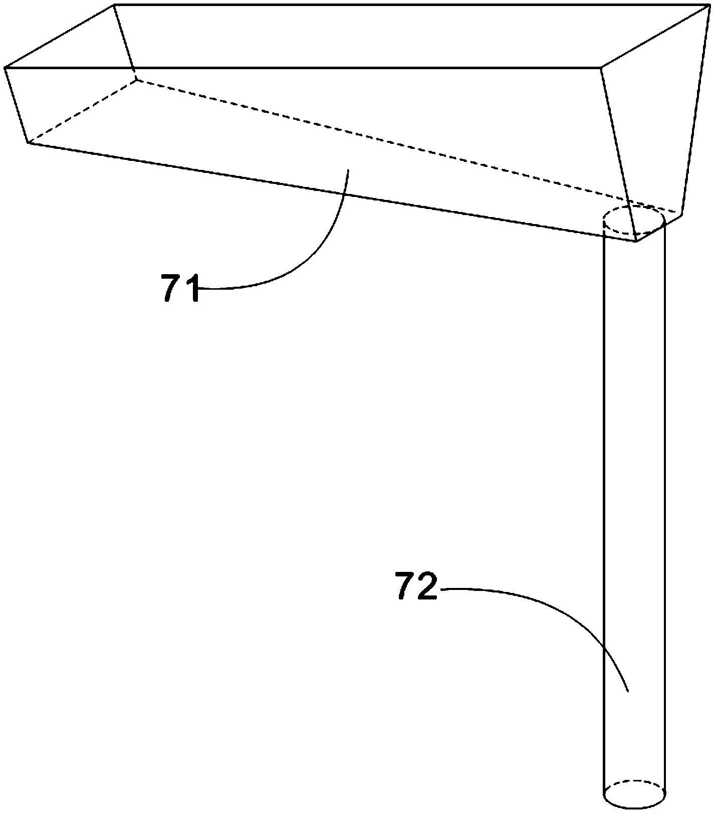
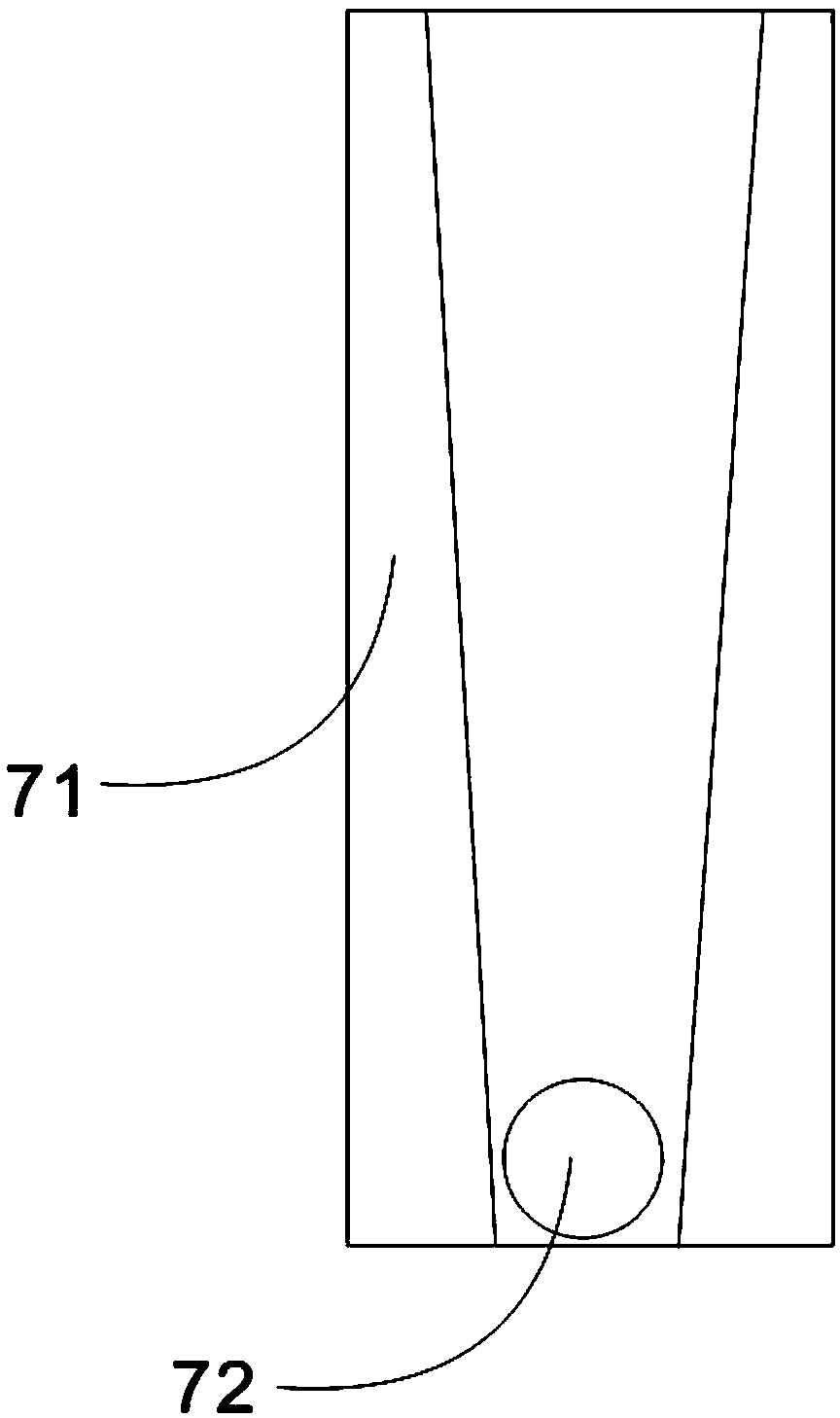
[0023] The present invention will be further described below in conjunction with accompanying drawing and specific embodiment:

[0024] Such as Figure 1 to Figure 7 As shown, the inoculant particle screening equipment of the present invention includes a platform 1, a mixing tank 2, a storage bin 3, a vibrating screen 4, a frame 5, a hopper 6, a recovery device 7, a discharge channel 8 and a timer 9; The silo 3 comprises a silo cover 31, a silo body 32, a silo bottom 33, a discharge port 34 and a support 35, the silo cover 31 and the silo bottom 33 are respectively located at the upper and lower ends of the silo body 32, and the discharge port 34 is located at the bottom of the storehouse 33. Bottom, warehouse cover 31 tops are provided with breach, and support 35 is installed on warehouse body 32 both sides, and the volume of storage bin 3 is preferably 2m 3 , which can ensure continuous production without stopping the machine; the mixing tank 2 is installed above the platfo...


PUM


Abstract

The invention discloses inoculant particle screening equipment which is characterized by comprising a platform, a stirring barrel, a storage bin, a vibrating screen, a rack, a hopper and a recovery device, wherein the stirring barrel is arranged above the platform, a discharge end of the stirring barrel is connected with the storage bin, the vibrating screen is positioned below the storage bin, the storage bin and the vibrating screen are positioned on one side of the platform, the rack is arranged on the other side of the platform, a conveyor belt is arranged on the rack and is connected with a power mechanism, the hopper is connected with the rack by virtue of the conveyor belt, the recovery device is positioned below the feed end of the stirring barrel; and a dust collection opening is formed in one side of the top of the storage bin, a filter screen is arranged on the dust collection opening, and a dust collector is arranged on the filter screen.

Description

technical field [0001] The invention relates to the field of inoculant production, in particular to an inoculant granule screening device. Background technique [0002] Cast iron is basically a eutectic alloy composed of iron, carbon and silicon, of which carbon mainly exists in the form of graphite; to produce high-quality castings, it is crucial to control the morphology of graphite formed when cast iron solidifies and the matrix metal structure ;Inoculation treatment is one of the most important links in the production process; a good inoculation treatment can make the cast iron have a microstructure that meets the requirements, thereby ensuring the mechanical properties and processing properties of the casting; adding an inoculant to the liquid cast iron can form a large amount of The submicroscopic core promotes the formation of eutectic clusters in the liquid phase; when the eutectic solidification temperature is close to the eutectic solidification temperature, fine g...

Claims


Application Information

Patent Timeline
IPC IPC(8): B01F15/00B01F15/02B07B1/28B07B1/46B01D46/10
Inventor 韩岗马银强林志国
Owner 成都宏源铸造材料有限公司
Why Eureka
Try Eureka