Automatic machining equipment for supporting wheel side covers

A technology for processing equipment and rollers, which is used in metal processing equipment, metal processing mechanical parts, and other manufacturing equipment/tools, etc., and can solve the problems of increased production costs, many operators, and long processing cycles.

Inactive Publication Date: 2014-12-17
泉州市华盛机械设备有限公司
View PDF6 Cites 10 Cited by
  • Summary
  • Abstract
  • Description
  • Claims
  • Application Information

AI Technical Summary

Problems solved by technology

Two roller side covers are installed at both ends of the wheel body of each track roller, and unlike the wheel body of the track roller, the side covers of the track roller are generally not rotators, and the processing process is more complicated, so the supporting weight The production efficiency of the wheel side cover seriously restricts the production efficiency of the rollers
[0003] like figure 1 The structure of the general track roller side cover is shown. Traditionally, ordinary milling machines or drilling machines are used to process such track wheel side covers. Because the track roller side covers have multiple mounting holes for matching with other parts and With the plane, the size, processing position and processing position of each mounting hole are different. For threaded holes, tapping and other processes are required. The processing positions and processing accuracy of each flat and flat plane are also different. Multiple milling machines or drilling machines are required. Equipment for processing, the roller side cover needs multiple positioning and clamping during the processing

Method used


Image

  • Automatic machining equipment for supporting wheel side covers
  • Automatic machining equipment for supporting wheel side covers
  • Automatic machining equipment for supporting wheel side covers

Examples


Embodiment Construction

[0029] The present invention will be further described below in conjunction with the accompanying drawings and specific embodiments.

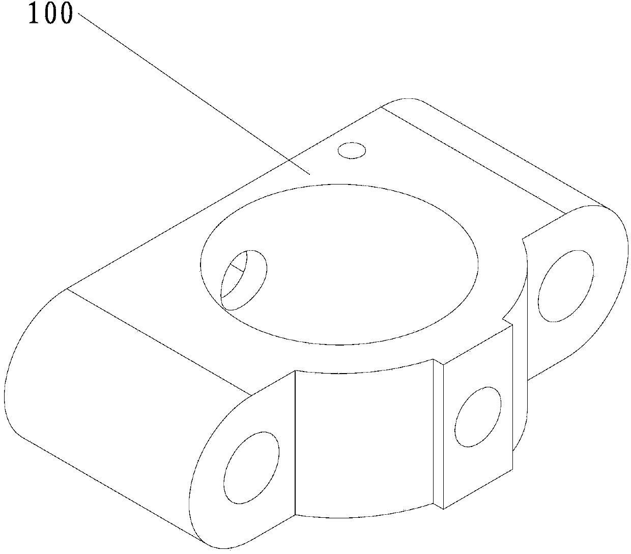
[0030] like figure 1 Shown is the track roller side cover 100 to be processed by the processing equipment of this embodiment. The blank of the track roller side cover 100 is a casting or forging, and the track roller side cover 100 needs to be processed before processing. The central hole and the two side surfaces serve as positioning holes and positioning surfaces. Of course, those skilled in the art can make appropriate adjustments to the structure of the roller side cover 100 as required. The positioning hole and / or the positioning surface can also choose other positions according to actual needs.

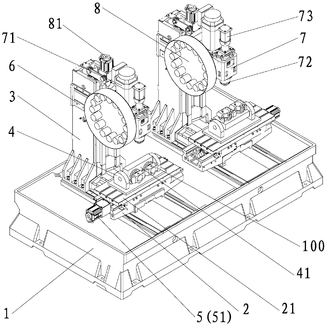
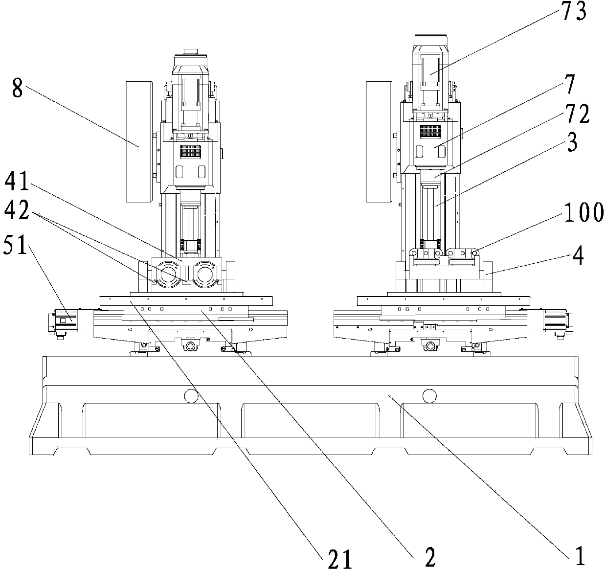
[0031] like Figure 2-Figure 5 As shown, the automatic processing equipment for the roller side cover provided by this embodiment includes a control device (not shown in the figure), a base 1, a saddle 2 and a column 3 arranged on the base 1, a...


PUM


Abstract

The invention provides automatic machining equipment for supporting wheel side covers. The automatic machining equipment for supporting wheel side covers comprises a control device, a base, saddles and stand columns, wherein a clamping mechanism, a clamping driving mechanism and a saddle driving mechanism are installed on each saddle, an installation rack is arranged on each stand column, one end of each installation rack is fixedly connected onto the corresponding stand column, a spindle box is installed at the other end of each installation rack, a servo motor, a cutter installation part and a cutter driving mechanism are respectively installed on each spindle box, and the control device controls the operation time sequence of the clamping driving mechanism, the saddle driving mechanisms, the servo motors and the cutter driving mechanisms. Therefore, the machining of a plurality of installation holes and a plurality of planes can be finished in one clamping step only, and the machining accuracy is higher; since all machining processes are finished on the same equipment, the production line is short, the risk that semi-finished products are damaged or oxidized during transfer is avoided during machining, the reject rate of products is lower and the production efficiency is effectively improved.

Description

technical field [0001] The invention relates to a processing equipment for the side cover of the supporting wheel required for construction machinery such as excavators and bulldozers or military machinery such as tanks, in particular to an automatic processing equipment for the side cover of the supporting wheel. Background technique [0002] The track roller is a part of the four-wheel belt of tracked construction machinery such as excavators and bulldozers or tracked military machinery such as tanks. It is mainly used to support the weight of such construction machinery or military machinery and let the track move along the wheels. Two roller side covers are installed at both ends of the wheel body of each track roller, and unlike the wheel body of the track roller, the side covers of the track roller are generally not rotators, and the processing process is more complicated, so the supporting weight The production efficiency of the wheel side cover seriously restricts th...

Claims


Application Information

Patent Timeline
IPC IPC(8): B23P23/00B23Q1/25B23Q5/36B23Q3/06B23Q3/155
CPCB23P23/00B23Q1/25B23Q3/06B23Q3/155B23Q5/36
Inventor 杨元赞
Owner 泉州市华盛机械设备有限公司
Why Eureka
Try Eureka