Gravity offset energy electricity generation device
A technology of gravity and energy, applied in the direction of engines, mechanical equipment, machines/engines, etc., can solve the problems of large investment and large area, and achieve the effect of small investment, no noise, and simple equipment
- Summary
- Abstract
- Description
- Claims
- Application Information
AI Technical Summary
Problems solved by technology
Method used
Image

Examples
Embodiment 1
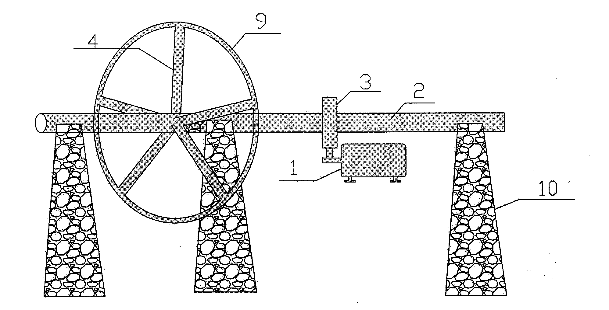
[0025] Dig a pit on the ground with a length of 17m, a width of 3m, and a depth of 8m. The surrounding of the pit is poured with reinforced concrete to form a runner foundation with a thickness of 500mm and a height of 9m. The main shaft protrudes 1.5m outward on the basis of 3m width, and there is a drive wheel at its end. The main shaft is fixed on the foundation through bearings and bearing seats. The diameter of the main shaft is used for welding the arm part, and the remaining shaft diameter is 500mm.
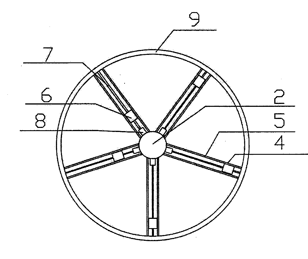
[0026] The main shaft is welded with 4 arms (lever) made of steel at the side of the center. The arms are evenly distributed on the upper, lower, left, and right sides of the main shaft. The center distance of the arms is 785mm. m, welded into a hollow square column with steel. The inner cavity is 6.8m in length, 0.68m in width and 0.68m in height, and the inside is flat and smooth.
[0027] There are bearing wheels around the counterweight in the cavity of the arm to re...
Embodiment 2
[0031] Dig a pit on the ground with a length of 20m, a width of 3m, and a depth of 10m. The surrounding of the pit is poured with reinforced concrete to form a runner foundation with a thickness of 600mm and a height of 11m. The main shaft protrudes 2m outward on the basis of 3m width, and there is a transmission wheel at the end. The main shaft is fixed on the foundation through bearings and bearing seats. The diameter of the main shaft is except for the middle part used to weld the arm, and the rest of the shaft diameter is 600mm.
[0032] Weld 5 support arms (lever) made of steel against the center of the runner foundation below the main shaft. The support arms are evenly distributed on the top, bottom, left, and right sides of the main shaft. 940mm, 940mm high, welded into a hollow square column with steel. The inner cavity is 8.9m long, 0.84m wide, and 0.84m high, and the inside is flat and smooth.
[0033] There are bearing wheels around the counterweight body in the c...
Embodiment 3
[0037] Dig a pit about 12m deep and 5m wide on a flat site, use reinforced concrete or stones to make a solid foundation and retaining wall around the pit, and do a good job of waterproofing.
[0038] Install the prefabricated 1m-diameter main shaft (rotation shaft) on the foundation frame through seat tiles or bearings, and then weld 5 pieces with an outer diameter of 500mm, a wall thickness of 30mm, and a length of 11m evenly distributed on one side of the main shaft. The cylindrical support arm, the top of the support arm is welded together with a steel plate with a width of 500 mm and a thickness of 30 mm. The inside of the support arm is required to be smooth so as to double as a slideway for the counterweight.
[0039]On the support arm, the work window is reserved through the support arm, and the counterweight, hydraulic equipment and electrical equipment with a weight of one ton or design weight are placed in the slideway of the support arm, the hydraulic equipment and ...
PUM
 Abstract
Description
Claims
Application Information