High-energy electronic igniter circuit

A high-energy electronics and igniter technology, applied in the electrical field, can solve the problem of easy burning of resistance and achieve the effects of not easy to burn out, low cost, and low resistance consumption

Inactive Publication Date: 2014-12-17
NANJING CHANG ENERGY MEASUREMENT & CONTROL EQUIP
View PDF5 Cites 3 Cited by
  • Summary
  • Abstract
  • Description
  • Claims
  • Application Information

AI Technical Summary

Problems solved by technology

And the gross power of the resistor is I 2 R≈290W, after full-wave rectification, the four 1K/50W resistors will burn out a

Method used


Image

  • High-energy electronic igniter circuit
  • High-energy electronic igniter circuit
  • High-energy electronic igniter circuit

Examples


Embodiment Construction

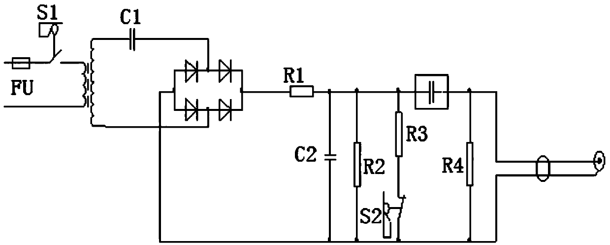
[0015] The present invention is described in detail below in conjunction with accompanying drawing:

[0016] Such as figure 1 As shown, a high-energy electronic igniter circuit of the present invention includes a step-up transformer, a resistor R1, a resistor R2, a resistor R3, a capacitor C1, a capacitor C2, a switch S1, a switch S2, a discharge tube and a rectifier circuit, the switch S1 and the booster The primary coil of the transformer is connected in series, the capacitor C1 is connected in series with the secondary coil of the step-up transformer, the input terminal of the rectifier circuit is connected with the secondary coil of the step-up transformer, and the output terminal of the rectifier circuit is respectively connected with one end of the resistor R1 and one end of the capacitor C2 , the other end of the resistor R1 is connected to the other end of the capacitor C2, the resistor R2 is connected in parallel with the capacitor C2, the switch S2 is connected in se...


PUM


Abstract

The invention discloses a high-energy electronic igniter circuit. The high-energy electronic igniter circuit comprises a boosting transformer, a resistor R1, a resistor R2, a resistor R3, a resistor R4, a capacitor C1, a capacitor C2, a switch S1, a switch S2, a discharge tube and a rectifying circuit, wherein the switch S1 is connected in series with a primary coil of the boosting transformer; the capacitor C1 is connected in series with a secondary coil of the boosting transformer; the input end of the rectifying circuit is connected with the secondary coil of the boosting transformer; the output end of the rectifying circuit is connected with one end of the resistor R1 and one end of the capacitor C2 respectively; the other end of the resistor R1 is connected with the other end of the capacitor C2; the resistor R2 is connected in parallel with the capacitor C2; the switch S2 is connected in series with the resistor R3, and is then connected in parallel with the capacitor C2; the resistor R4 is connected in parallel with the capacitor C2; a voltage output end is connected with a spark plug. The high-energy electronic igniter circuit has the beneficial effects that the transformer can work for a long time through capacitive current limiting, is prevented from being burnt out easily, is safe to overhaul, and is low in cost; the internal resistance consumption is low.

Description

technical field [0001] The invention relates to the electrical field, in particular to a high-energy electronic igniter circuit. Background technique [0002] During the engineering application of our company's high-energy oil gun igniter circuit in the early stage, the phenomenon of transformer burnout and current-limiting resistor burnout occurred continuously, which affected production. After research, it is found that the power of the current limiting resistor R1 is too small. After the 2500V AC is full-wave rectified, the 6uFC1 energy storage capacitor is charged through the R1 current limiting resistor. When the discharge value of the discharge tube reaches 2500V, the electric energy stored in C1 is equal to the point The musket tip discharges. The charging current is i=(U-U 0) / r ×e -t / τ ), the average current is calculated to be about 270mA by substituting the data, or calculated according to the output power of 20 joules per frequency after the full-wave rectific...

Claims


Application Information

Patent Timeline
IPC IPC(8): F23Q3/00H02M7/213
Inventor 昌健
Owner NANJING CHANG ENERGY MEASUREMENT & CONTROL EQUIP
Why Eureka
Try Eureka