
Panoramic surveillance camera shooting system of cockpit

A camera system and aircraft cockpit technology, applied in the field of aircraft cockpit panoramic monitoring system, to achieve the effect of meeting airtight test conditions, convenient layout, and convenient use

Active Publication Date: 2014-12-17
沈阳飞机设计研究所扬州协同创新研究院有限公司
View PDF8 Cites 9 Cited by
  • Summary
  • Abstract
  • Description
  • Claims
  • Application Information

AI Technical Summary

Problems solved by technology

The radio transceiver device will be interfered by external high-intensity electromagnetic waves, so information can only be transmitted through wireless optical transmission.

Method used


Image

  • Panoramic surveillance camera shooting system of cockpit
  • Panoramic surveillance camera shooting system of cockpit
  • Panoramic surveillance camera shooting system of cockpit

Examples


Embodiment Construction

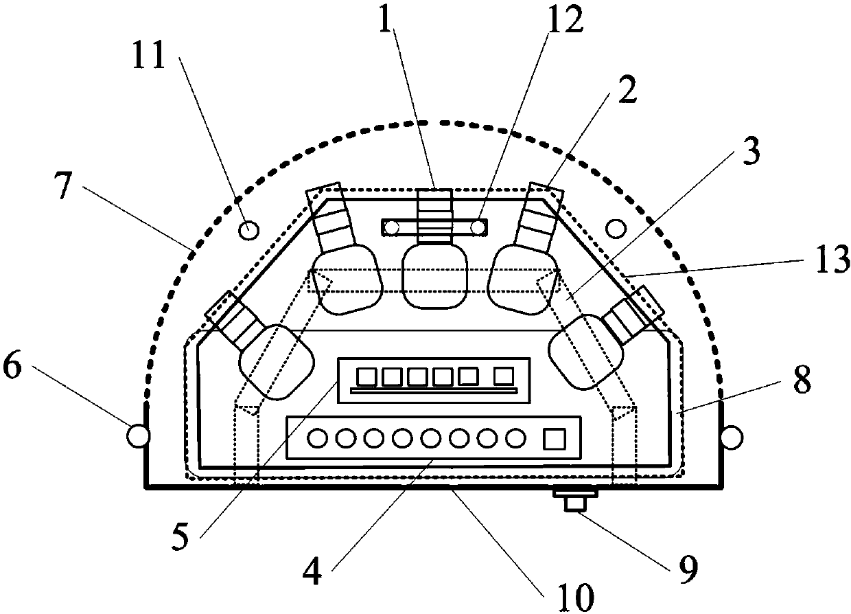
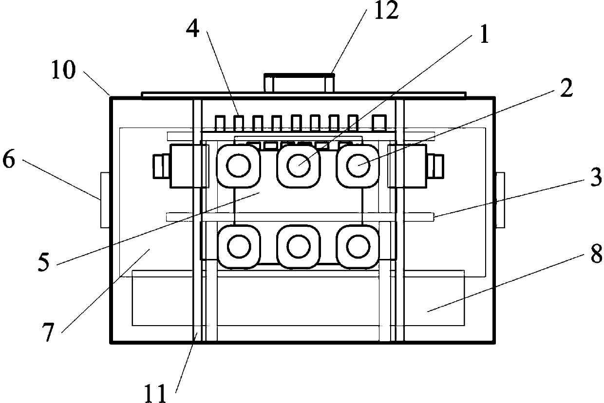
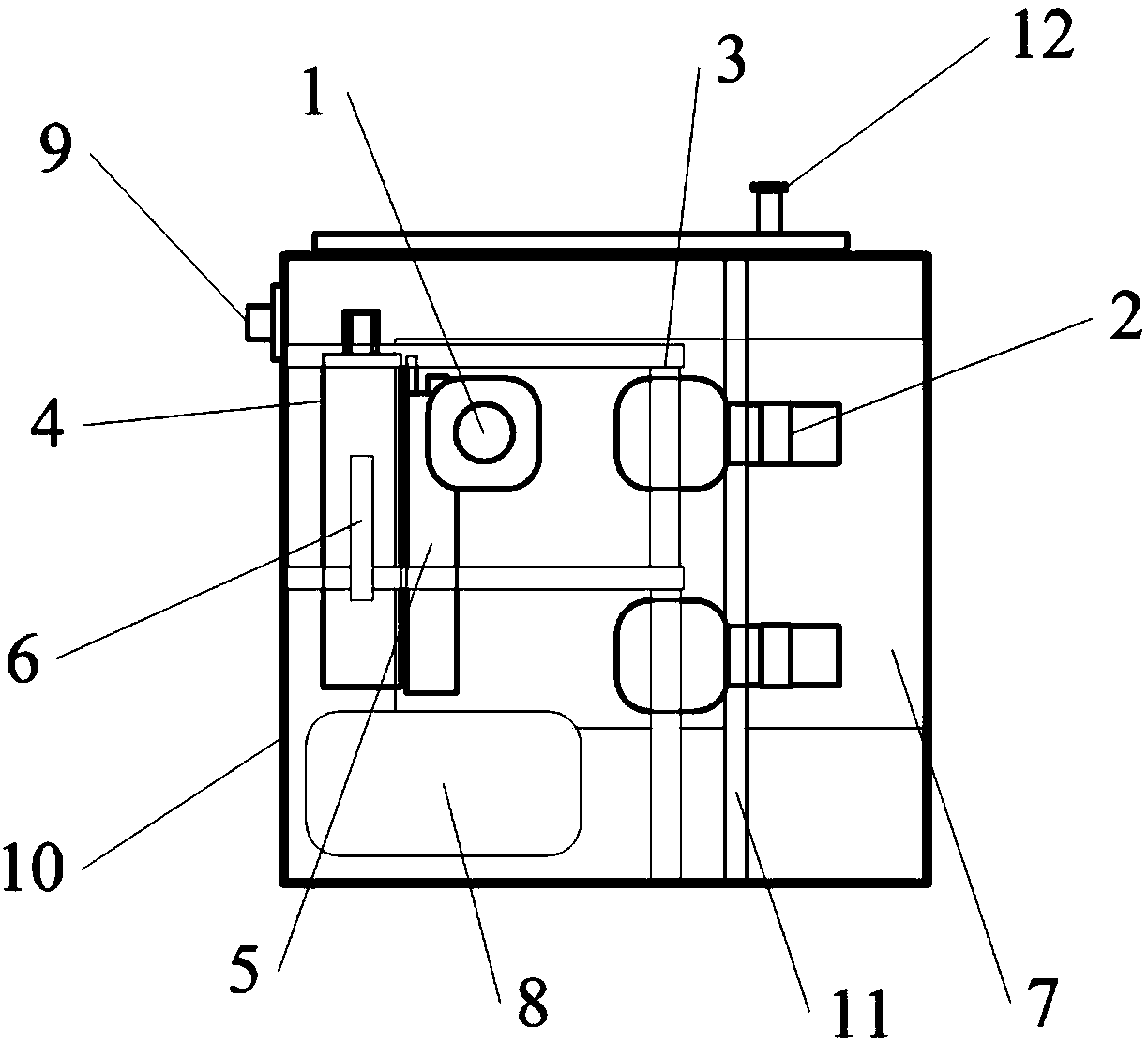
[0040]According to the different monitoring requirements of the object display information, select lenses of different specifications and various small cameras, fix them on double-layer or multi-layer brackets, adjust the angle and lens of each camera module, so that it can not only cover the entire forward monitoring range, and can focus on local monitoring of sensitive monitoring areas. All video signals are converted electro-optical through the transmitter module of the optical transceiver, and then transmitted to the receiving module of the optical transceiver outside the test area through the optical fiber. Angle panoramic images and local key monitoring images, all monitoring equipment and supporting equipment are placed in a small shielded housing, and its front end is a composite structure of arc-shaped light-transmitting materials and metal mesh, which ensures the normal operation of the entire video acquisition system and protects the environment at the same time. The...


PUM


Abstract

A panoramic surveillance camera shooting system of a cockpit is characterized by comprising a video capture sub system and a wireless optical transmission sub system. The video capture sub system comprises wide-range camera shooting modules (1), long-focus local camera shooting modules (2), a fixing support (3), a lightware-terminal-equipment transmitting module (4), an integrated power supply module (5), external fixed handles (6), an arc-shaped light-transmitting material and metal mesh composite structure (7), a high-capacity battery pack (8), a fiber interface (9), an electromagnetic shielding shell (10), a shielding door (12) and a beryllium copper spring (13). The wireless optical transmission sub system comprises a wireless transmission module shell (14), rubber cushions (15), an optical antenna (16), fixed magnet sets (17), a fiber interface (18) and a communication optical fiber (19). By the panoramic surveillance camera shooting system, normal operation of the whole video capture system is guaranteed while circuits are protected from influences of high-radio-frequency electromagnetic radiation.

Description

technical field [0001] The invention relates to the structural design and application field of a monitoring camera device, and in particular provides an aircraft cockpit panoramic monitoring system that is resistant to strong radio frequency radiation and works in a high-intensity electromagnetic field environment. Background technique [0002] At present, when conducting high-field-strength electromagnetic radiation sensitivity tests on some special airborne aviation products, real-time monitoring of the entire aircraft cockpit system is required. The existing surveillance systems that can withstand a certain intensity of radio frequency electromagnetic radiation are all single-camera systems, which cannot perform large-angle panoramic observation of the surveillance object. It is not only impossible to observe and compare many monitoring objects in the cockpit at the same time, but also takes a long time and is inefficient. And because it adopts external power supply, the...

Claims


Application Information

Patent Timeline
IPC IPC(8): H04N7/18H04N7/22
Inventor 张少卿刘树彬吕朝辉许小林
Owner 沈阳飞机设计研究所扬州协同创新研究院有限公司
Learn More