Welding clamping device

A welding clip and positioning slider technology, applied in welding equipment, welding equipment, auxiliary devices, etc., can solve the problems of long time, affect processing efficiency, affect welding efficiency, etc., achieve easy clamping and unloading, and improve welding quality. , The effect of improving welding efficiency

Active Publication Date: 2014-12-24
CRRC QINGDAO SIFANG CO LTD
View PDF8 Cites 11 Cited by
  • Summary
  • Abstract
  • Description
  • Claims
  • Application Information

AI Technical Summary

Problems solved by technology

In the welding process, the existing welding fixtures generally use bead-type welding fixtures that can only clamp a single workpiece to be welded, which seriously affects the efficiency of the process. In addition, when the welding fixture is clamped and unloaded, the bolts need to be screwed repeatedly, which takes a lon

Method used


Image

  • Welding clamping device

Examples


Embodiment 2

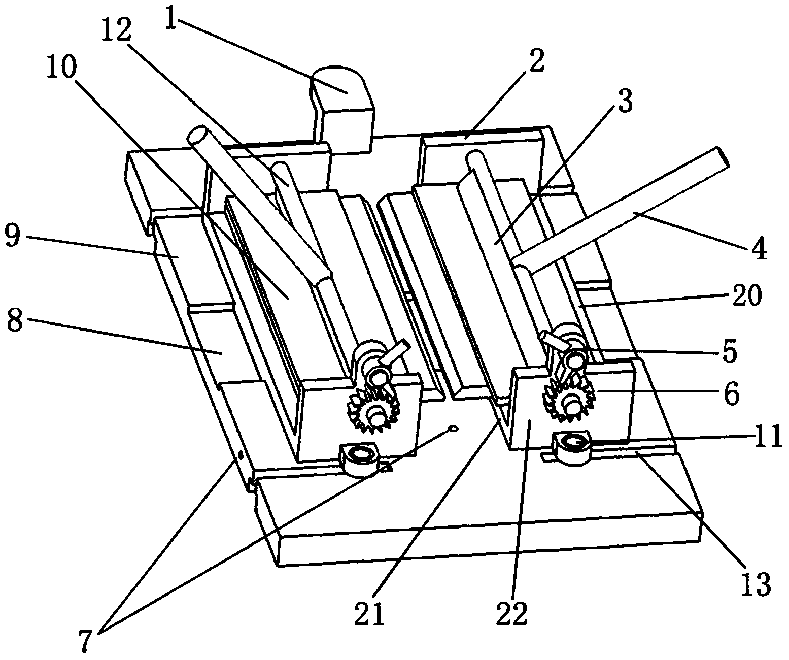
[0026] This embodiment is the same as Embodiment 1, and the difference is that in this embodiment, the clamping device also includes two sets of linear modules respectively installed on both sides of the positioning slider, and each set of linear modules includes Servo motor and ball screw, the ball screw has two screw rods with opposite helical directions, each screw rod is provided with a nut; the two positioning sliders are respectively connected with the two nuts of the ball screw; the ball screw is connected with the servo motor . The ball screw is installed on the bottom plate 9, parallel to the chute, and the servo motor drives the ball screw to rotate, thereby driving the two positioning sliders 2 that are oppositely arranged to approach or move away from each other.


PUM


Abstract

The invention relates to the technical field of auxiliary welding equipment and discloses a welding clamping device. The welding clamping device comprises a soleplate and two positioning sliding blocks, wherein each positioning sliding block comprises a sliding seat and a cam, and the sliding seat comprises a supporting plate and two cam frames which are fixedly arranged at the two opposite ends of the supporting plate; the cam is rotatably installed between the two cam frames through a cam shaft and is used for pressing a workpiece to be welded; the soleplate is provided with a sliding slot, and the two positioning sliding blocks are oppositely and slidably installed in the sliding slot. According to the welding clamping device, two workpieces to be welded can be clamped, and the workpieces to be welded are better positioned, so that the welding quality is improved; the welding clamping device has the advantages of easiness in clamping and unloading, no need of repeatedly screwing bolts, short consumed time and improvement on the welding efficiency.

Description

technical field [0001] The invention relates to the technical field of welding auxiliary equipment, in particular to a welding clamping device. Background technique [0002] With the development of industrial production, people's requirements for production efficiency are getting higher and higher. Laser-MIG hybrid welding (laser melting pole inert gas shielded hybrid welding) is widely used. In the welding process, the existing welding fixtures generally use bead-type welding fixtures that can only clamp a single workpiece to be welded, which seriously affects the efficiency of the process. In addition, when the welding fixture is clamped and unloaded, the bolts need to be screwed repeatedly, which takes a long time. , affecting welding efficiency; the clamping of the workpiece is not firm enough, which may easily cause the workpiece to break during processing, wasting costs and reducing efficiency. The heat input of laser-MIG hybrid welding is large, the back is exposed ...

Claims


Application Information

Patent Timeline
IPC IPC(8): B23K37/04B23K26/70
CPCB23K37/04B23K26/348B23K37/0408B23K37/0443B23K26/702B23K37/0435
Inventor 张世欣邓小军刘韶庆孟立春王小成李世涛张占岭董丽
Owner CRRC QINGDAO SIFANG CO LTD
Why Eureka
Try Eureka