Slugging machine for plastic bottle

A technology for plastic bottles and cutting machines, which is applied in metal processing and other directions, can solve the problems of difficult debugging and complex structure, and achieve the effects of stable surface quality of the cut, simplified mechanism and simple debugging.

Inactive Publication Date: 2014-12-24
四川美可迪科技开发有限责任公司
View PDF8 Cites 10 Cited by
  • Summary
  • Abstract
  • Description
  • Claims
  • Application Information

AI Technical Summary

Problems solved by technology

[0009] In order to overcome the defects of complex structure and difficult debugging of the above-mentioned plastic bottle cutting machine, the present invention provides a plastic bottle cutting machine. The plastic bottle cutting machine has a simple structure, short debugging time, low cost of the whole machine, and can be popularized and applied in small and medium-sized enterprises

Method used


Image

  • Slugging machine for plastic bottle
  • Slugging machine for plastic bottle
  • Slugging machine for plastic bottle

Examples


Embodiment 1

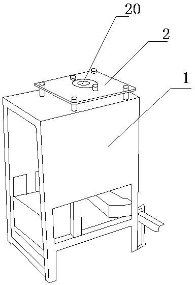
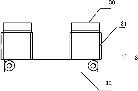
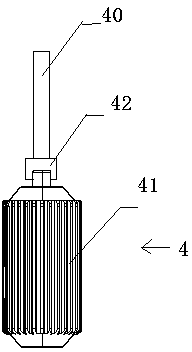
[0050] What present embodiment provides is the notch machine that is used for plastic bottle notch, and notch machine comprises frame 1, cutter mechanism 3, plastic bottle fixed frame 2 and driving mechanism, and described plastic bottle fixed frame 2 is installed on frame 1 top, The plastic bottle fixing frame 2 is provided with a plastic bottle feeding port 20, and the cutter mechanism 3 and the driving mechanism are all fixed on the frame 1, and the driving mechanism includes a cutter rotating mechanism 4 and a cutter opening and closing mechanism 5, and the plastic bottle The feeding port 20 is arranged facing the cutter mechanism 3 .

[0051] The plastic bottle fixing frame 2 is fixed on the frame 1 by bolts. There are multiple plastic bottle fixing frames 2. The size of the plastic bottle feeding inlet 20 of each plastic bottle fixing frame 2 is different, and workers can choose according to different specifications of plastic bottles. The plastic bottle fixing frame of ...

Embodiment 2

[0059]This embodiment is basically the same as Embodiment 1, except that the up and down drive mechanism of the conical push block is different. The up and down drive mechanism of the conical push block in this embodiment includes a cam shaft 514, a cam 515, a cam swing arm 516 and a cam top The rod 517 and the cam 515 are sleeved on the camshaft 514, one end of the cam swing arm 516 is hinged on the frame 1, and the other end is connected with the cam push rod 517, the cam swing arm 516 is pressed on the cam 515, and the cam swing arm 516 is connected A cam extension spring 518 is arranged, and the other end of the cam extension spring 518 is connected on the frame 1, and the bottom of the cam push rod 517 is connected with the tapered push block 51, and the camshaft 514 is provided with a crank handle 519. In this embodiment, the extension spring 53 is no longer used to urge the arc arm 50 to return, but a volute spring is used to urge the arc arm to return. The worm spring i...

Embodiment 3

[0061] This embodiment is basically the same as Embodiment 1, except that the upper and lower drive mechanisms of the conical push block are different. on the rack. The opening and closing action of the cutter is realized by controlling the extension and retraction of the ejector rod of the cylinder to control the up and down movement of the conical push block.


PUM


Abstract

The invention relates to a slugging machine for a plastic bottle. The slugging machine comprises a stand, a cutter mechanism, a plastic bottle fixing rack and a driving mechanism, wherein the plastic bottle fixing rack is arranged on the top of the stand; the plastic bottle fixing rack is arranged at a feeding hole of the plastic bottle; the cutter mechanism and the driving mechanism are fixed on the stand; the driving mechanism comprises a cutter rotating mechanism and a cutter opening and closing mechanism; the feeding hole of the plastic bottle just faces to the cutter mechanism. The slugging machine for the plastic bottle is simple in structure, short in debug time and low in manufacturing cost of the whole machine, thus being popularized and applied in middle and small-sized enterprises.

Description

technical field [0001] The invention relates to a plastic bottle forming equipment, in particular to a plastic bottle cutting equipment. Background technique [0002] Plastic bottles are made of polyester (PET), polyethylene (PE), polypropylene (PP) as raw materials, after adding corresponding organic solvents, after high temperature heating, blow molding, extrusion blowing, or injection molding through plastic molds Plastic containers and plastic bottles are not easy to break and low in cost. After the plastic bottle is formed on the blow molding machine, its mouth is closed and cannot be directly used for filling. Therefore, it is necessary to cut off the excess part of the bottle mouth. The traditional method is that workers use a cutter to cut off the excess part of the bottle mouth. The main defects of this cutting method are: low work efficiency, inconsistent surface quality and inconsistent size of the cut , which seriously affects the normal operation of the subseq...

Claims


Application Information

Patent Timeline
IPC IPC(8): B26D1/29B26D7/26B26D7/01B26D5/08
Inventor 周云凯
Owner 四川美可迪科技开发有限责任公司
Why Eureka
Try Eureka