Supersonic flame spraying system

A technology of supersonic flame and spraying gun, which is applied in coating, fusion spraying, metal material coating process, etc., and can solve the problems of high spraying cost, large oxygen consumption, and affecting coating quality, etc.

Active Publication Date: 2014-12-24
WUHU DINGHAN REMFR TECH
View PDF4 Cites 10 Cited by
  • Summary
  • Abstract
  • Description
  • Claims
  • Application Information

AI Technical Summary

Problems solved by technology

There are many variables involved in the supersonic flame spraying system, and the control system is complicated. Once the control system fails, it may not only damage the spraying equipment itself, but also cause quality problems of the sprayed workpiece.
The current supersonic flame spraying basically uses pure oxygen as a combustion aid, which consumes a lot of oxygen.
For example: the oxygen consumption of a supersonic flame spray gun using propane, propylene, etc. as fuel exceeds 3 bottles / h, the spraying materials are difficult to be effectively controlled and compressed, and the spraying cost is relatively high
In the supersonic flame spraying process, the gun barrel is often blocked due to the unreasonable setting of the spraying parameters. The gun barrel blockage will directly lead to the phenomenon of large molten droplets during the spraying process, which will seriously affect the coating quality. The supply of materials and the precise control of the spraying process of the spraying system will not be conducive to the promotion of supersonic flame spraying technology
[0005] At the same time, due to the unreasonable pipeline design and installation and connection of the existing supersonic flame spraying, the safety performance is relatively low, and the control range of the gas flow rate or the powder delivery flow rate is limited, and it is impossible to achieve hierarchical control, which brings a lot of trouble to the operator. Trouble comes, the time spent on adjustment is poor, and the operation efficiency is low

Method used


Image

  • Supersonic flame spraying system
  • Supersonic flame spraying system
  • Supersonic flame spraying system

Examples


Embodiment Construction

[0045] In order to make the technical means, creative features, goals and effects achieved by the present invention easy to understand, the present invention will be further described below in conjunction with specific illustrations.

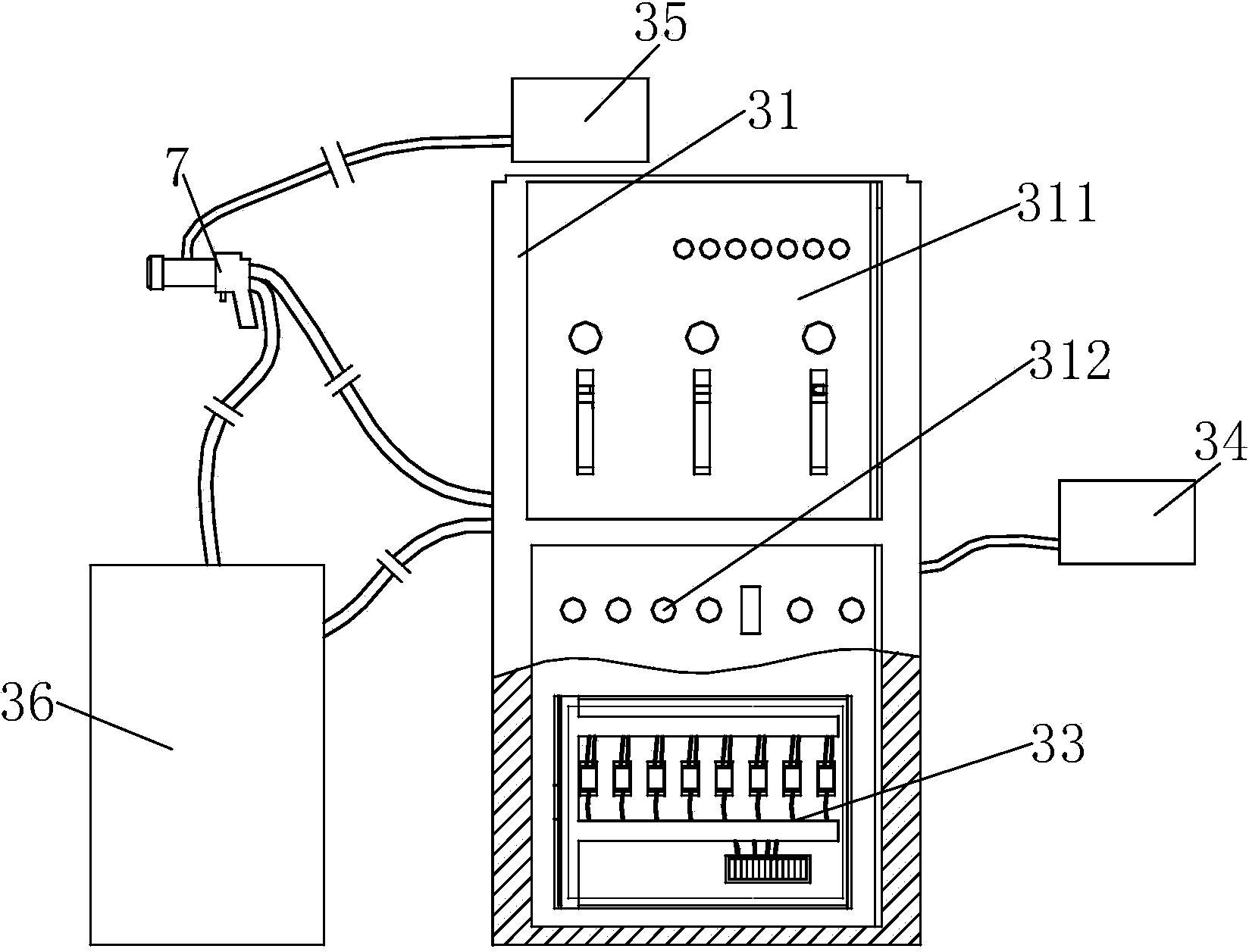
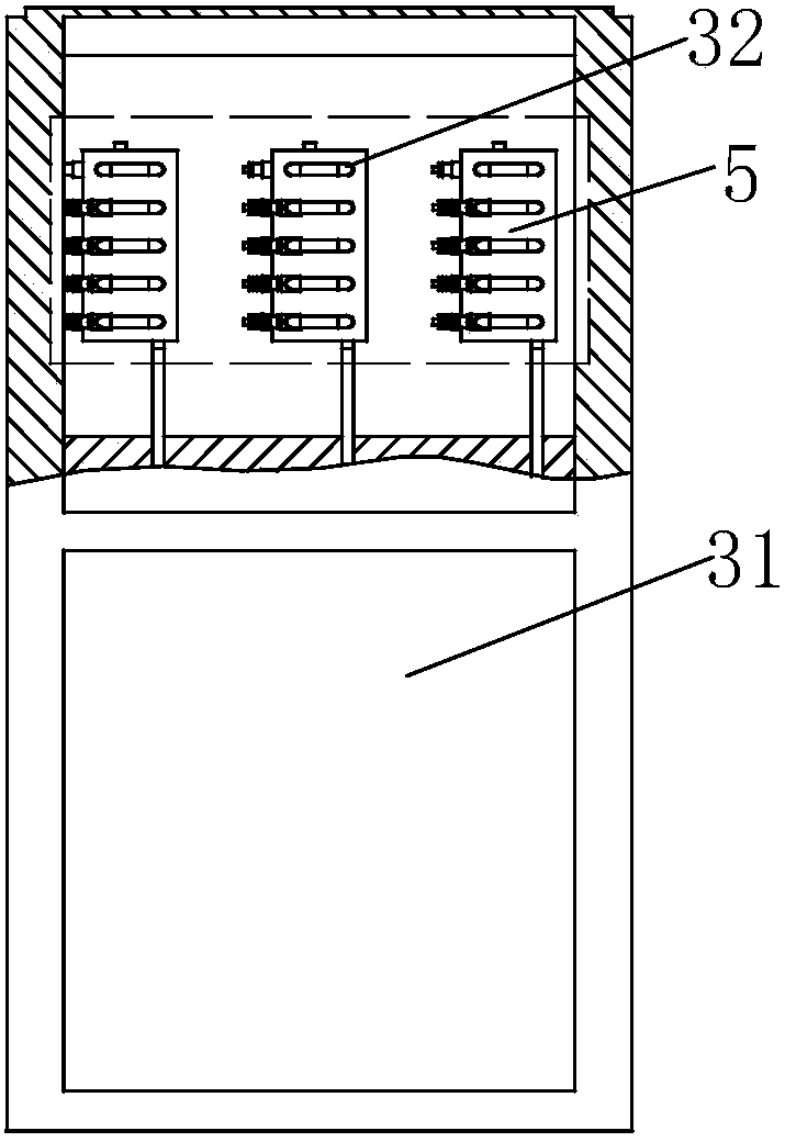
[0046] like figure 1 , figure 2 , image 3 , Figure 4 and Figure 5 As shown, a supersonic flame spraying system includes a control cabinet 31, an execution system 32, a control circuit 33, a tank group 34, a chiller 35, a powder feeder 36 and a spray gun 7, and the upper side of the front end of the control cabinet 31 is A display interface 311 is provided at the position, and a control interface 312 is provided at the lower side of the front end of the control cabinet 31; the execution system 32 is located above the interior of the control cabinet 31, and the control circuit 33 is located below the interior of the control cabinet 31; The tank group 34 is connected to the execution system 32 through pipelines, the chiller 35 is connected ...


PUM


Abstract

The invention relates to a supersonic flame spraying system. The supersonic flame spraying system comprises a control cabinet, an execution system, a control circuit, a group of tanks, a cooling water machine, a powder feeder and a spraying gun, wherein a display interface is arranged at the upper side of the front end of the control cabinet, and a control interface is arranged at the lower side of the front end of the control cabinet; the execution system is arranged at the upper part inside the control cabinet, and the control circuit is arranged at the lower part inside the control cabinet; the group of tanks is connected with the execution system by virtue of pipelines, the cooling water machine is connected with the spraying gun by virtue of a pipeline, one side of the powder feeder is connected with the execution system by virtue of a pipeline, the other side of the powder feeder is connected with the spraying gun by virtue of a pipeline, and the spraying gun is connected with the execution system by virtue of a pipeline. The supersonic flame spraying system has the advantages of reasonable structural design, easiness in operation and control and high safety performance, automation degree is high, manpower is saved, hydrogen is effectively prevented from refluxing, and personal safety of an operator is guaranteed.

Description

technical field [0001] The invention relates to the technical field of thermal spraying, in particular to a supersonic flame spraying system. Background technique [0002] Supersonic flame spraying includes supersonic oxygen flame spraying and supersonic air flame spraying. In the existing equipment, there are several types of heat sources such as flame, plasma, and electric arc, and the working gas or working liquid is also different, but both adopt Laval nozzle or equal-section nozzle to obtain supersonic speed. For example, supersonic flame spraying uses combustible gas such as hydrogen, propane or propylene or liquid fuel such as aviation kerosene to mix with oxygen and ignites in the combustion chamber. The violently expanding gas is restricted by the nozzle to form a supersonic high-temperature flame flow, and the powder flows along the combustion chamber. The axis is fed by an inert gas such as nitrogen, heated and accelerated to be ejected. [0003] Supersonic flam...

Claims


Application Information

Patent Timeline
Patent Type & Authority Applications(China)
IPC IPC(8): C23C4/12C23C4/129
Inventor 程敬卿薛卫昌
Owner WUHU DINGHAN REMFR TECH
Why Eureka
Try Eureka