FRP (fiber reinforced plastic) sectional material-concrete combined structure adopting novel combined interface

A combined structure and concrete technology, which is applied in the direction of building construction and construction, can solve problems such as limited connection/bonding ability, limited popularization and application, and corrosion of steel connectors, so as to achieve flexible layout of shear keys, avoid steel corrosion, The effect of improving the carrying capacity

Inactive Publication Date: 2014-12-24
ZHENGZHOU UNIV
View PDF3 Cites 3 Cited by
  • Summary
  • Abstract
  • Description
  • Claims
  • Application Information

AI Technical Summary

Problems solved by technology

The connection / bonding capacity of the combined interface between FRP profiles and concrete connected by direct pouring is often limited; while the combined interface between FRP profiles and concrete bonded by pure epoxy adhesive has low bearing capacity and is prone to local peeling; the shear force of steel bolts The key connection method needs to punch holes on the surface of the FRP profile, which will weaken the profile to a certain extent, and at the same time, the steel connector has the problem of corrosion
Due to the disadvantages of the existing FRP profiles and concrete composite interface connection methods to a certain extent limit the popularization and application of FRP profiles-concrete composite materials, so it is necessary to continue to improve the shear bearing capacity of the interface between FRP profiles and concrete connection method

Method used


Image

  • FRP (fiber reinforced plastic) sectional material-concrete combined structure adopting novel combined interface
  • FRP (fiber reinforced plastic) sectional material-concrete combined structure adopting novel combined interface
  • FRP (fiber reinforced plastic) sectional material-concrete combined structure adopting novel combined interface

Examples


Embodiment 1

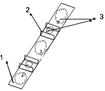
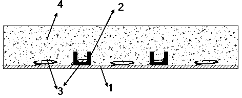
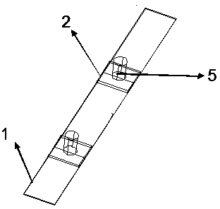
[0049] Such as figure 1 , figure 2 As shown, the FRP section bar-concrete composite structure provided by the present invention adopts the new combination interface, including FRP profile formwork 1, FRP shear force key 2, interface resin layer 3 and concrete 4; FRP shear force key 2 is arranged on the FRP profile formwork 1 surface; concrete 4 is poured directly on the surface of FRP profile formwork 1, which can save the traditional formwork required for traditional concrete pouring; FRP shear key 2, an interface resin layer is provided between the surface of FRP profile formwork 1 and concrete 4 3. The adhesive force is provided by the interface resin layer 3 .

[0050] The interface resin layer 3 is a wet bonding resin.

[0051] During specific construction, wet bonding resin must first be laid on the surface of the FRP profile formwork 1 including the surface of the shear bond 2, and the concrete 4 is poured on the surface of the FRP profile formwork 1 during the time...

Embodiment 2~3

[0082] In this example, the FRP profile-concrete beam structure is prepared by using the FRP profile-concrete composite structure of the new combination interface described in Example 1, and the specific situation is introduced as follows.

[0083] Example 2 and Example 3 FRP profile-concrete T-shaped composite beam specimens were prepared with the FRP profile-concrete composite structure of the new composite interface described in Example 1. The preparation method is the same as in Example 1, and the specific specifications of the prepared T-shaped composite beam test piece are: the length of the T-shaped composite beam beam is 3.2m, the clear span is 3.0m, and the tension zone at the bottom of the T-shaped beam is equipped with 2 20mm HRB335 grade steel bar. The size of the T-shaped section is 450mm×380mm×150 mm×80 mm (width of upper flange×height of section×width of web×thickness of upper flange). The FRP profile formwork of this embodiment is made by vacuum introduction ...

Embodiment 4~5

[0129] The main purpose of Examples 4-5 is to detect the fatigue performance of the FRP profile-concrete composite beam using the new composite interface and the fatigue performance of the new composite interface.

[0130] The specific specifications of the prepared FRP profile-concrete T-beam composite specimen are as follows: the beam length is 3.2 m, the clear span is 3.0 m; section height×web width×top flange thickness); there are 2 20mm HRB335 tension steel bar. The FRP profile-concrete T-beam composite specimen prepared in Examples 4 to 5 has the same cross-sectional form as in Examples 2 to 3, and the FRP profile formwork used is a U-shaped FRP profile. The difference between Example 4 and Example 5 The difference lies in the fiber layup at the bottom of the profile used by the two. The bottom of the FRP profile template is laid with unidirectional fiber cloth along the length of the beam, which mainly bears the tension. The fiber materials and layers laid on the bo...


PUM

PropertyMeasurementUnit
thicknessaaaaaaaaaa
tensile strengthaaaaaaaaaa
strengthaaaaaaaaaa

Abstract

The invention belongs to the technical field of a concrete structure, and particularly relates to an FRP (fiber reinforced plastic) sectional material-concrete combined structure adopting a novel combined interface. The structure comprises an FRP sectional material template, an FRC shear key, an interface resin layer and concrete, wherein the FRP shear key is arranged on the surface of the FRP sectional material template, the concrete is directly cast on the surface of the FRP sectional material template, and the interface resin layer is arranged among the cast-in-place concrete, the surface of the FRP sectional material template and the FRP shear key. The FRP sectional material-concrete combined structure adopting the novel combined interface provided by the invention has the advantages that the preparing process is simple and convenient, the operation is easy, meanwhile, higher designability is realized, the technical advantages of the existing wet bonding and steel screw bolt shear key are combined, the technical effect is more excellent, the technical defects that the FRP sectional materials and the concrete can easily peel and fall, the steel screw bolt shear key can easily get rusty and the perforation damage to the FRP sectional material can be easily caused can be more effectively overcome, and the popularization and the application of the FRP sectional material-concrete combined structure are favorably realized.

Description

technical field [0001] The invention belongs to the technical field of concrete structures, and in particular relates to an FRP profile-concrete composite structure adopting a novel composite interface. Background technique [0002] In the existing building construction technology, the durability of the infrastructure due to the corrosion of steel bars is severely reduced, causing huge economic losses. Statistics show that the economic loss caused by the corrosion of steel bars and steel products can generally reach 2-4% of the gross output value (GDP) of the national economy, such as about 3% in Europe, 4.2% in the United States and Australia, and 6-4% in Poland. 10%, and our country is about 6%. Therefore, improving the durability of infrastructure is an important issue facing the economic and social development of all countries in the world. [0003] The emergence of Fiber Reinforced Polymer (FRP) has brought hope for improving the durability of infrastructure. Compare...

Claims


Application Information

Patent Timeline
Patent Type & Authority Applications(China)
IPC IPC(8): E04B1/14E04B1/16E04B1/30
Inventor 张普吴刚高丹盈朱虹孟少平
Owner ZHENGZHOU UNIV
Why Eureka
Try Eureka