High-power LED (Light Emitting Diode) phase-change temperature control device with heat pipes

A technology for temperature control devices and LED packages, applied in the field of lighting, can solve the problems of reducing the temperature of LED chips, large volume changes in liquid-gas phase transitions, and additional energy consumption of active cooling systems, to achieve enhanced melting and solidification heat transfer, and improve effective Thermal conductivity, cost and weight reduction effects

Active Publication Date: 2014-12-24
XI AN JIAOTONG UNIV
View PDF10 Cites 6 Cited by
  • Summary
  • Abstract
  • Description
  • Claims
  • Application Information

AI Technical Summary

Problems solved by technology

Patent WO2009110987A1 discloses a heat storage system using phase-change materials for LED lamps. Its structure is to replace the traditional metal heat sink with a heat sink with a cavity. When the change material melts, it absorbs heat and stores energy to reduce the temperature of the LED chip. The disadvantage is that the thermal conductivity of the phase change material is low and the heat transfer capacity is limited.
Patent CN101776255A discloses a LED liquid-cooled heat dissipation structure, the principle of which is to circulate the fluid heat dissipation medium between the expansion buffer and three heat exchangers through a micro-pump, and then dissipate heat into the air through the lamp shell, which is insufficient The disadvantage is that the active cooling system used requires additional energy consumption and has poor reliability
Patent CN101782228A discloses a liquid-cooled high-power LED lamp. Its structure includes a substrate for fixing LED chips. The other side of the substrate is connected to the upper end of the heat pipe. The advantage is that the cantilever-shaped substrate base is used, which increases the thermal resistance between the heat pipe and the LED chip and deteriorates the heat transfer effect.
Patent CN101315927A discloses a high-power LED phase-change cooling device. Its principle is to use the liquid-gas phase change of the working medium to realize the thermal isothermal effect of the heat sink body to reduce the temperature of the LED chip. The disadvantage is that the volume change of the liquid-gas phase change is large. The heat sink has a large volume and uses metal foam as the boiling structure to suppress the natural convection of the phase change material
Patent US20090322229A1 discloses a new type of LED lighting device. Its principle is to transfer the heat of the LED chip to the phase-change material buried in the ground through the heat pipe to reduce the temperature of the LED chip. The disadvantage is that the application of this structure is limited. Not conducive to promotion

Method used


Image

  • High-power LED (Light Emitting Diode) phase-change temperature control device with heat pipes
  • High-power LED (Light Emitting Diode) phase-change temperature control device with heat pipes
  • High-power LED (Light Emitting Diode) phase-change temperature control device with heat pipes

Examples


Embodiment Construction

[0024] The present invention will be described in further detail below in conjunction with the accompanying drawings.

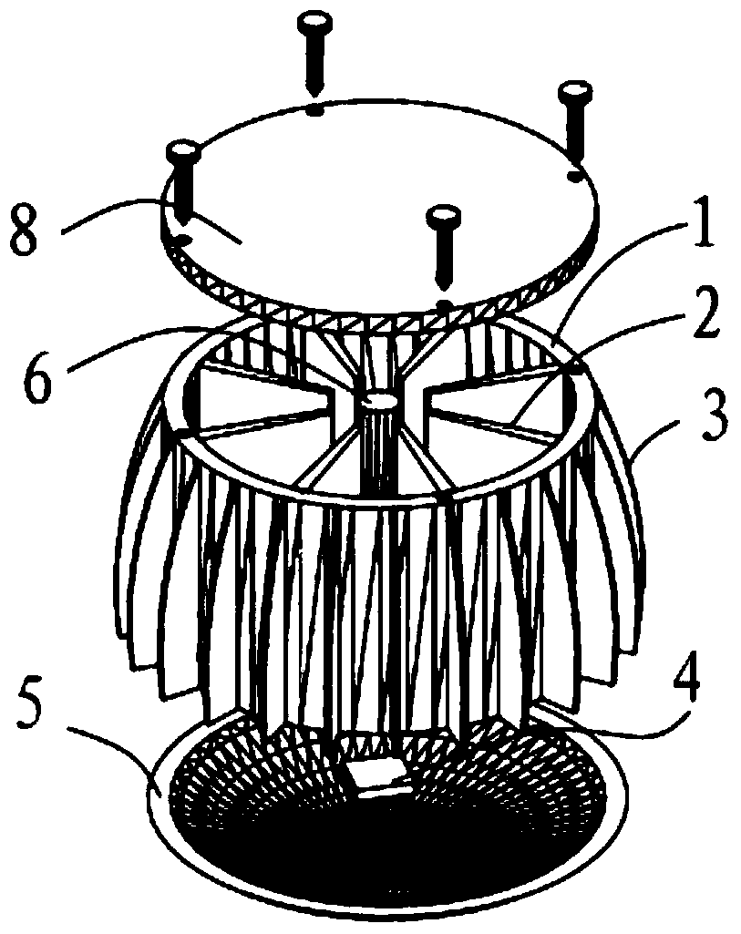
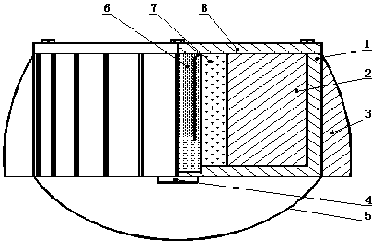
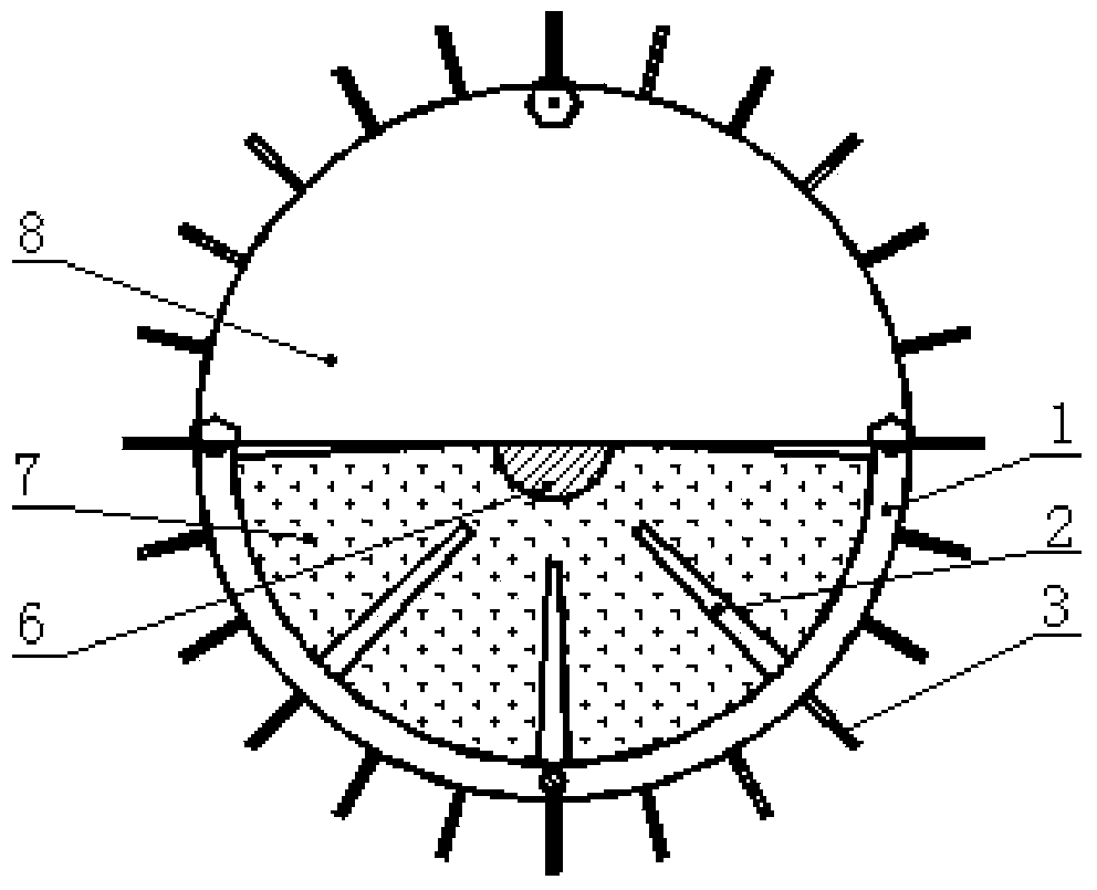
[0025] Such as figure 1 and figure 2 As shown, the high-power LED phase-change temperature control device with its own heat pipe in the present invention includes a circular heat sink cavity 1 with an LED package 4 at the bottom, and the LED package 4 is glued on by eutectic welding or heat-conducting silicone grease. The bottom of the heat sink cavity 1 and the bottom of the heat sink cavity 2 are also glued with a lens 5 for concentrating light and protecting the LED package 4; the lens 5 is made of transparent materials such as glass. The top of the heat sink cavity 1 is connected with a sealing end cover 8 by welding, gluing or bolts; a gravity heat pipe 6 filled with a working medium is arranged in the heat sink cavity 1, and the lower end of the gravity heat pipe 6 is connected by thread or interference The matching method is connected to the bottom ...


PUM


Abstract

The invention discloses a high-power LED (Light Emitting Diode) phase-change temperature control device with heat pipes. The device comprises a heat sink cavity of which the bottom is provided with an LED package, wherein N gravity assisted heat pipes and N groups of variable thickness fins are arranged in the heat sink cavity; each gravity assisted heat pipe is filled with a working medium; one group of variable thickness fins are radially arranged on the circumference of each gravity assisted heat pipe; each group of variable thickness fins consists of a plurality of variable thickness fins; on the outer side of each gravity assisted heat pipe, a space formed by the heat sink cavity and the corresponding variable thickness fins is filled with a phase-change material of which the melting point is lower than the normal working temperature of the LED package; the outer wall of the heat sink cavity is also provided with a plurality of variable height fins; the variable height fins are arranged along the circumference of the heat sink cavity. According to the device, heat dissipation and temperature control can be effectively performed on an intermittent high-power LED, the defect of low heat conductivity coefficient of the phase-change material is overcome, the use of an energy-consuming cooling scheme such as active cooling is avoided, the complexity of a system is reduced, and the package cost of the high-power LED is reduced.

Description

technical field [0001] The invention belongs to the lighting field, in particular to a high-power LED phase-change temperature control device with a heat pipe. technical background [0002] LED (Light Emitting Diode) has been widely used in night scene lighting, automobile light source, traffic light and general lighting, safety lighting and special lighting due to its advantages of energy saving, green environmental protection, long life and safety and reliability. However, LED luminescence belongs to solid luminescence. Its principle is to excite electrons and make electrons jump in energy level to realize light emission; the spectrum does not contain infrared part, and it is a cold light source, so the heat generated cannot be dissipated through radiation, and The actual efficiency of most LED lamps can only reach 20%, that is, 80% of the electric energy converted into heat can only be dissipated through the natural convection of the shell. The color of the LED changes a...

Claims


Application Information

Patent Timeline
Patent Type & Authority Applications(China)
IPC IPC(8): F21V29/00F21Y101/02
Inventor 屈治国汪辉汪天送
Owner XI AN JIAOTONG UNIV
Why Eureka
Try Eureka