Method for measuring air ratio and heat capacity ratio by vibration of piston in single-end sealed cylinder

A specific heat capacity ratio and sealing air technology, applied in the direction of analyzing materials, instruments, etc., can solve the problems that are difficult to realize, cannot be corrected quantitatively, and rotation uncertainty, etc., and achieve simple structure, simple and easy vibration method, and low cost Effect

Inactive Publication Date: 2014-12-24
SICHUAN UNIV
View PDF5 Cites 1 Cited by
  • Summary
  • Abstract
  • Description
  • Claims
  • Application Information

AI Technical Summary

Problems solved by technology

[0006] (2) The non-equivalence of the force above and below the small hole does not have the mechanical conditions of simple harmonic vibration: the thrust of the steel ball A on the upper and lower ends of the small hole is different, and the thrust on the lower end of the small hole is different. The thrust of the gas is large, the thrust on the upper end (the gas leaks from the small hole) is small, and the airflow environment in which the ball moves is abrupt. Both documents are skeptical about its principle; if there is no small hole, The steel ball is subjected to the thrust produced by the pressure difference, and the small ball will always rise without vibrating. Although, in the document "Improvement of the Experimental Method for Measuring the Specific Heat Capacity Ratio of Gas by Vibration Method", it is proposed to find the equilibrium position of the steel ball below the small hole , and then produce a vibration with an amplitude of about 1cm. Due to the lack of external force, it is difficult to achieve only through the adjustment of the air flow. The reason is that the steel ball will descend when the air flow is small, the steel ball will rise when the air flow is large, and the steel ball will be stable when the air flow is appropriate. Then After the steel ball stabilizes, the airflow must be increased to promote its rise. After rising for a certain distance, it must continue to return to a suitable airflow so that the thrust generated by the pressure difference is equal to the gravity. This step is difficult to achieve;
[0007] (3) The steel ball A will rotate and collide with the tube wall during the movement: the literature "Improvement of the Experimental Method for Measuring the Specific Heat Capacity Ratio of Gases by the Vibration Method" also found the phenomenon of rotation (called spin in the literature) and collision. We found that the reflected light of ball A changed during the vibration process, and then we drew a cross on the surface of steel ball A with a red marker pen, and found that the cross of steel ball A rotated during the vibration process, and different instruments and different The direction of its rotation is also changing over time. This result shows us that the surface of the pipe wall or / and the steel ball A is not uniform, causing the steel ball A to rotate under asymmetric force. We also found that the frequency of its rotation is between Different instruments and different times also show differences. In other words, the steel ball A is not in a laminar flow environment, but has a certain turbulent flow, and its rotational kinetic energy will affect the accuracy of the measurement. Moreover, due to the uncertainty of the rotation, it cannot Quantitatively corrected

Method used


Image

  • Method for measuring air ratio and heat capacity ratio by vibration of piston in single-end sealed cylinder
  • Method for measuring air ratio and heat capacity ratio by vibration of piston in single-end sealed cylinder

Examples


Embodiment Construction

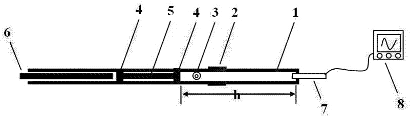
[0013] A cylinder 1 is made of hard transparent materials, such as glass and hard plastic, which can withstand pressure and have relatively small (negligible) deformation caused by pressure; the cylinder is divided into two sections, one of which is It is a hollow cylinder with a sealed bottom. A pressure sensor 7 is arranged at the bottom of the seal. The probe of the pressure sensor is located inside the cylinder 1. The signal line of the pressure sensor is connected to the digital oscilloscope 8, and the change of the pressure inside the cylinder is displayed by the digital oscilloscope. Curve, so as to measure its period; the other section of the cylinder 1 is a hollow tube, the inner diameter of the hollow tube and the hollow cylinder is the same, and its internal radius is recorded as r. Sealing gasket is arranged at place, and sealing gasket is the same as the sealing gasket of water cup, water valve etc., belongs to prior art.

[0014] The outer surface of cylinder 1 h...


PUM


Abstract

The invention relates to a method for measuring an air ratio and a heat capacity ratio by vibration of a piston in a single-end sealed cylinder. The transparent cylinder with an internal radius of r comprises two sections; the bottom end of one section is sealed and a pressure sensor is arranged on the one section; a signal wire of the pressure sensor is connected to a digital oscilloscope to measure a vibration period of T; a millimeter graduation ruler and a spirit bubble are arranged on the outer surface of the cylinder in the length direction of the cylinder; the two-position sealed piston with a mass of m and a piston connecting rod are arranged inside the cylinder; the piston connecting rod can be attracted by a magnetic field; one magnet extends into the hollow round tube end of the cylinder and is in contact with the piston, the magnetic field attracts stainless steel of the piston connecting rod, then the piston connecting rod is pulled towards the open end of the cylinder, and when the magnetic field force is smaller than a force generated by air pressure difference, the two-position sealed piston is separated from the magnet and vibrates and a meter measures an atmospheric pressure value P of the air; the air ratio and the heat capacity ratio are calculated according to the formula gamma=4pimh / (r<2>T<2>P). The method has the benefits that the sealed air has excellent elasticity; the experiment principle is more rigorous; vibration in the method is strict simple harmonic vibration; the rotating phenomenon cannot be generated; a vibration starting method is simple and easy to operate; a structure is simpler and cost is lower.

Description

technical field [0001] The invention relates to the measurement of physical constants, in particular, it provides a method for measuring air specific heat ratio by vibration method. Background technique [0002] Vibration method to measure specific heat capacity ratio of air is a commonly used method for measuring specific heat capacity ratio. The measurement method used in the physics laboratory, the experimental principle is detailed in "Improvement of the experimental method for measuring gas specific heat capacity ratio by vibration method", Journal of Taizhou University, December 2010 No. Volume 32, Issue 6, Page 39-42, "2 Experiments", and "Experimental Analysis of Air Specific Heat Capacity Ratio Measurement by Vibration Method, Laboratory Science, Volume 16, Issue 3, June 2013, Issue 35-37" "1.1 Principles of the original experiment". [0003] The principle adopted by the prior art, see figure 1 , the gas injection port injects gas continuously and stably, and the ...

Claims


Application Information

Patent Timeline
Patent Type & Authority Applications(China)
IPC IPC(8): G01N7/00
Inventor 饶大庆朱俊雍志华罗明蓉李娟邹旭敏王维果穆万军胡再国程艳梁雅庭刘石丹田野中于白茹李伟李紫原梁小冲
Owner SICHUAN UNIV
Why Eureka
Try Eureka