
Optical fiber coupler, manufacturing method of optical fiber couplers and detection method for packaging efficacy losing of optical fiber couplers

A technology of optical fiber coupler and optical fiber, which is applied in the coupling of optical waveguide, liquid tightness measurement using liquid/vacuum degree, etc., can solve the problems of increased insertion loss, improve reliability, improve stability, reduce water The effect of peak loss

Inactive Publication Date: 2014-12-24
深圳朗光科技有限公司
View PDF5 Cites 4 Cited by
  • Summary
  • Abstract
  • Description
  • Claims
  • Application Information

AI Technical Summary

Problems solved by technology

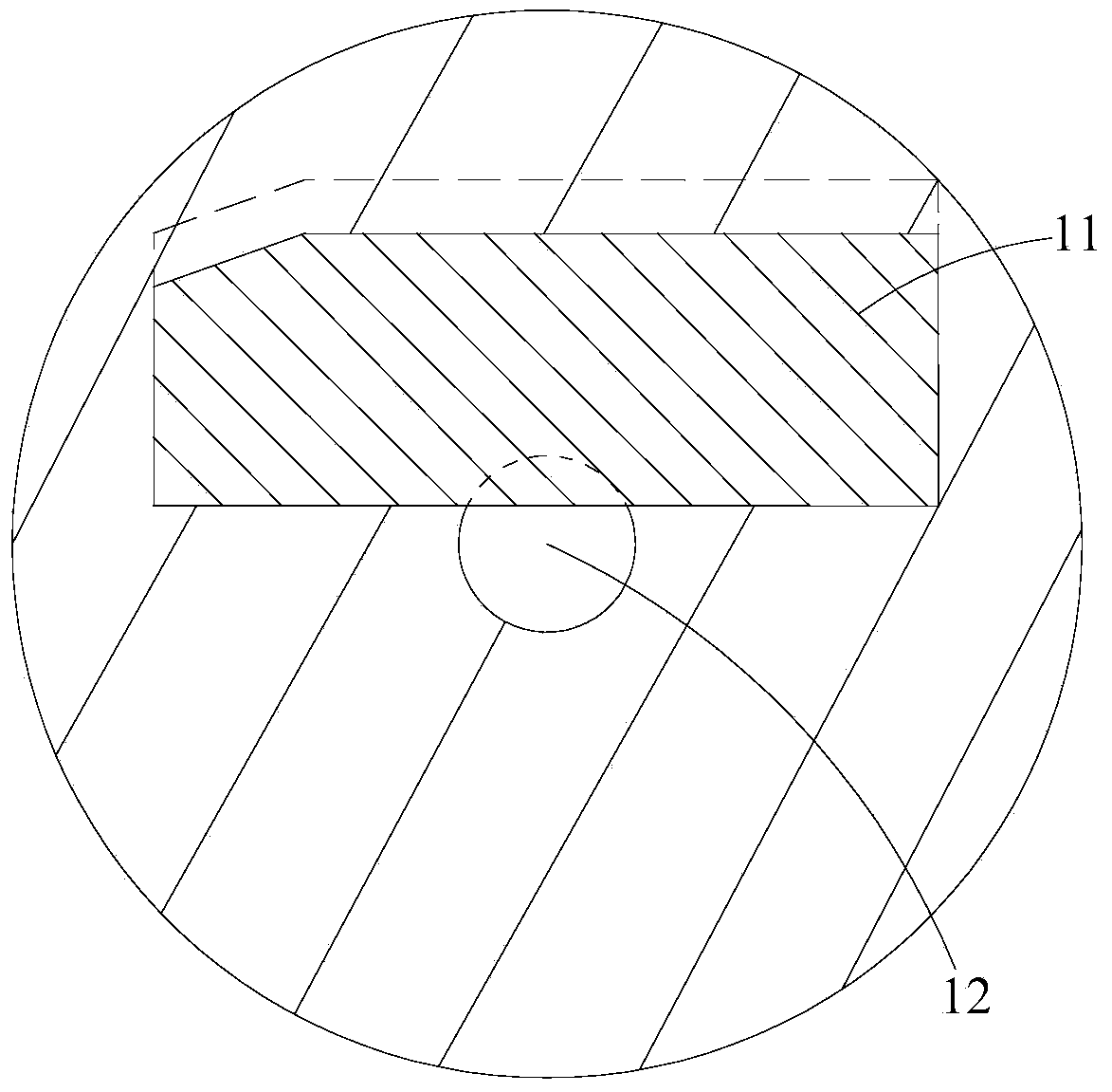
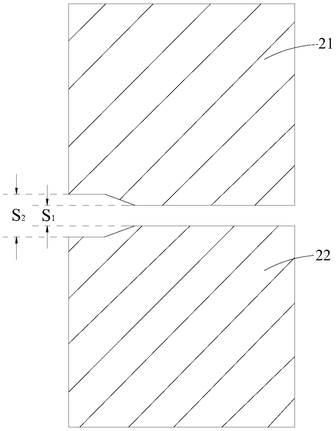
[0008] The purpose of the present invention is to provide an optical fiber coupler and its preparation method and a detection method for packaging failure, aiming to solve the problem of increased insertion loss of traditional loose tube optical fiber couplers at low temperature in the prior art

Method used


Image

  • Optical fiber coupler, manufacturing method of optical fiber couplers and detection method for packaging efficacy losing of optical fiber couplers
  • Optical fiber coupler, manufacturing method of optical fiber couplers and detection method for packaging efficacy losing of optical fiber couplers
  • Optical fiber coupler, manufacturing method of optical fiber couplers and detection method for packaging efficacy losing of optical fiber couplers

Examples


Embodiment Construction

[0046] In order to make the object, technical solution and advantages of the present invention clearer, the present invention will be further described in detail below in conjunction with the accompanying drawings and embodiments. It should be understood that the specific embodiments described here are only used to explain the present invention, not to limit the present invention.

[0047] The implementation of the present invention will be described in detail below in conjunction with specific embodiments.

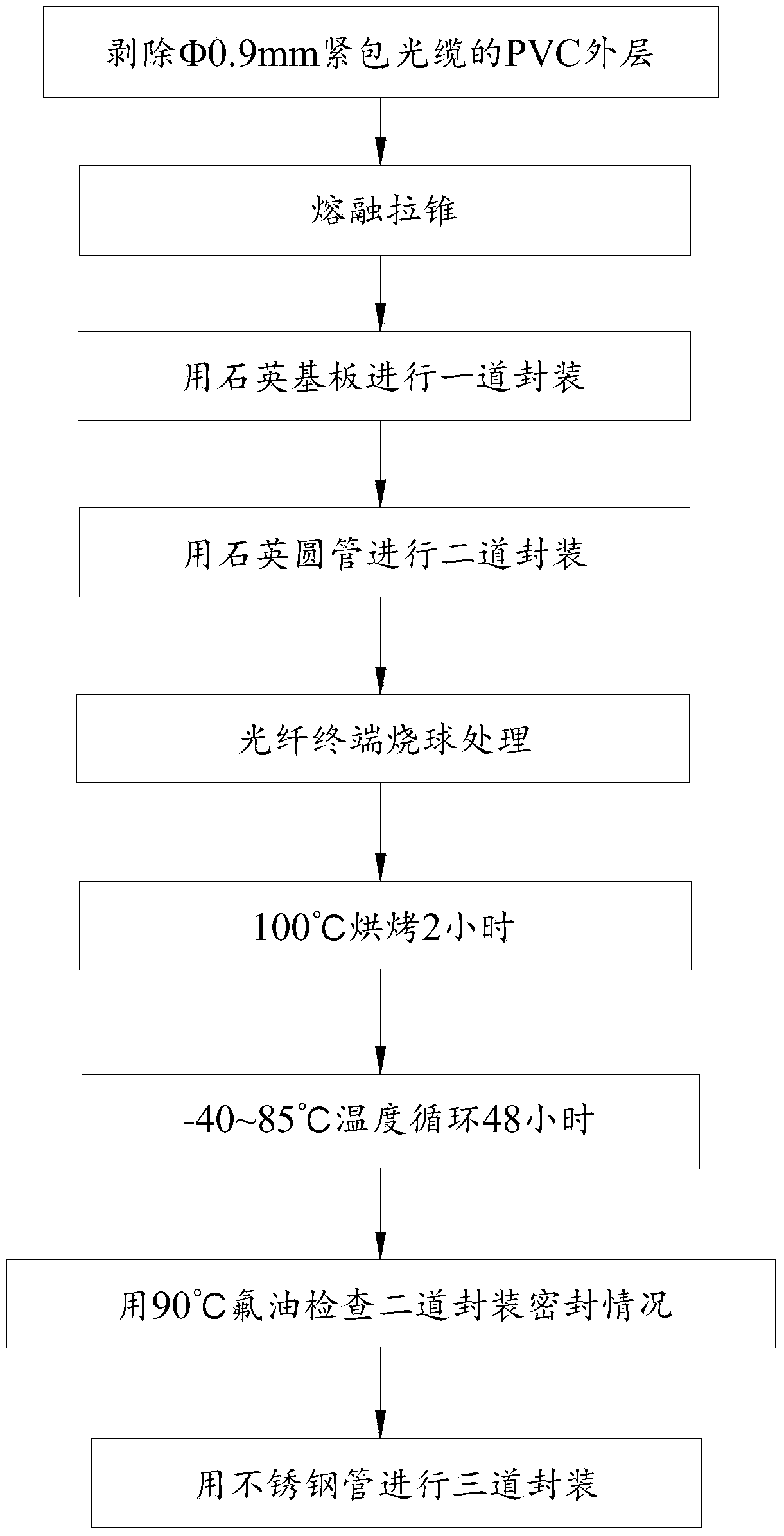
[0048] Such as figure 1 Shown, for the preparation flow diagram of the fiber coupler in the embodiment provided by the present invention, the preparation method of the present invention is introduced in detail below, and the realization process is:

[0049] Step 1: Strip the PVC outer layer of the optical cable without damaging the coating layer of the optical fiber, and melt the ring-cut PVC outer layer on the optical cable.

[0050] In this example, Φ0.89-0.91mm optic...


PUM


Abstract

The invention relates to the technical field of optical fiber couplers, and discloses an optical fiber coupler, a manufacturing method of optical fiber couplers and a detection method for packaging efficacy losing of the optical fiber couplers. The manufacturing method includes the steps of stripping an optical cable PVC outer layer; manufacturing the optical fiber couplers with the parallel clamping fused biconical taper process, and detecting the longitudinal tensile strength of the optical fiber couplers through pulling force after completion of sintering; conducting primary packaging on the sintered semi-finished products; then conducting secondary packaging on the sintered semi-finished products; conducting hot bulb processing on terminals of optical fibers; placing the semi-finished products in the environment with the temperature ranging from 95 DEG C to 105 DEG C for baking for 1.5 hours to 2.5 hours, cooling the semi-finished products to the normal temperature, placing the semi-finished products in the environment with the temperature ranging from -40 DEG C to 85 DEG C for circulating for 45 hours to 51 hours, checking the sealing condition of secondary packaging through fluorine-contained oil with the temperature ranging from 85 DEG C to 95 DEG C, and screening defective products; conducting tertiary packaging on the qualified semi-finished products. By means of the manufacturing method of the optical fiber couplers, the problem that insertion losses of traditional optical fiber couplers in the low-temperature state are increased is solved, and the stability of the optical fiber couplers is improved.

Description

technical field [0001] The invention relates to the technical field of fiber optic couplers, and discloses a fiber optic coupler, a preparation method thereof, and a detection method for packaging failure. The fiber optic coupler plays the role of splitting and combining optical signals, and is used in optical fiber communication, CATV, Fiber optic gyroscopes, fiber optic hydrophones, and fiber optic sensors are widely used in many fields. Background technique [0002] Fiber optic couplers play the role of splitting and combining optical signals, and are widely used in many fields such as fiber optic communication, CATV, fiber optic gyroscope, fiber optic hydrophone and fiber optic sensing. [0003] The fusion tapering method is currently the most mature and convenient method for preparing fiber couplers. When using the fusion tapering method to prepare the fiber coupler, the coating layer of two or more Φ0.25mm optical fibers should be stripped first, and then the fibers s...

Claims


Application Information

Patent Timeline
IPC IPC(8): G02B6/255G01M3/02
Inventor 丘奕凤朱少军岳超瑜叶铭森
Owner 深圳朗光科技有限公司
Learn More