
All solid-state plasma near coupling cloaking antenna array and control method thereof

A plasma antenna and plasma technology, applied in the antenna array, antenna, antenna coupling and other directions, can solve the problem that the antenna is difficult to hide, and achieve the effect of low cost, large gain, and compact and simple antenna structure

Inactive Publication Date: 2014-12-24
NANJING UNIV OF AERONAUTICS & ASTRONAUTICS
View PDF2 Cites 11 Cited by
  • Summary
  • Abstract
  • Description
  • Claims
  • Application Information

AI Technical Summary

Problems solved by technology

[0005] Purpose of the invention: In order to solve the problem that the antenna is difficult to stealth in the prior art, and realize reconfigurability, electrical scanning and low cost at the same time, the present invention provides an all-solid-state plasma proximity coupling stealth antenna array, which solves the deficiencies of the prior art

Method used


Image

  • All solid-state plasma near coupling cloaking antenna array and control method thereof
  • All solid-state plasma near coupling cloaking antenna array and control method thereof
  • All solid-state plasma near coupling cloaking antenna array and control method thereof

Examples


Embodiment Construction

[0018] The present invention will be further explained below in conjunction with the accompanying drawings.

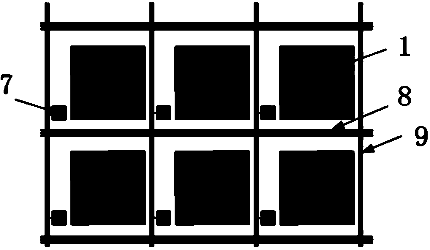
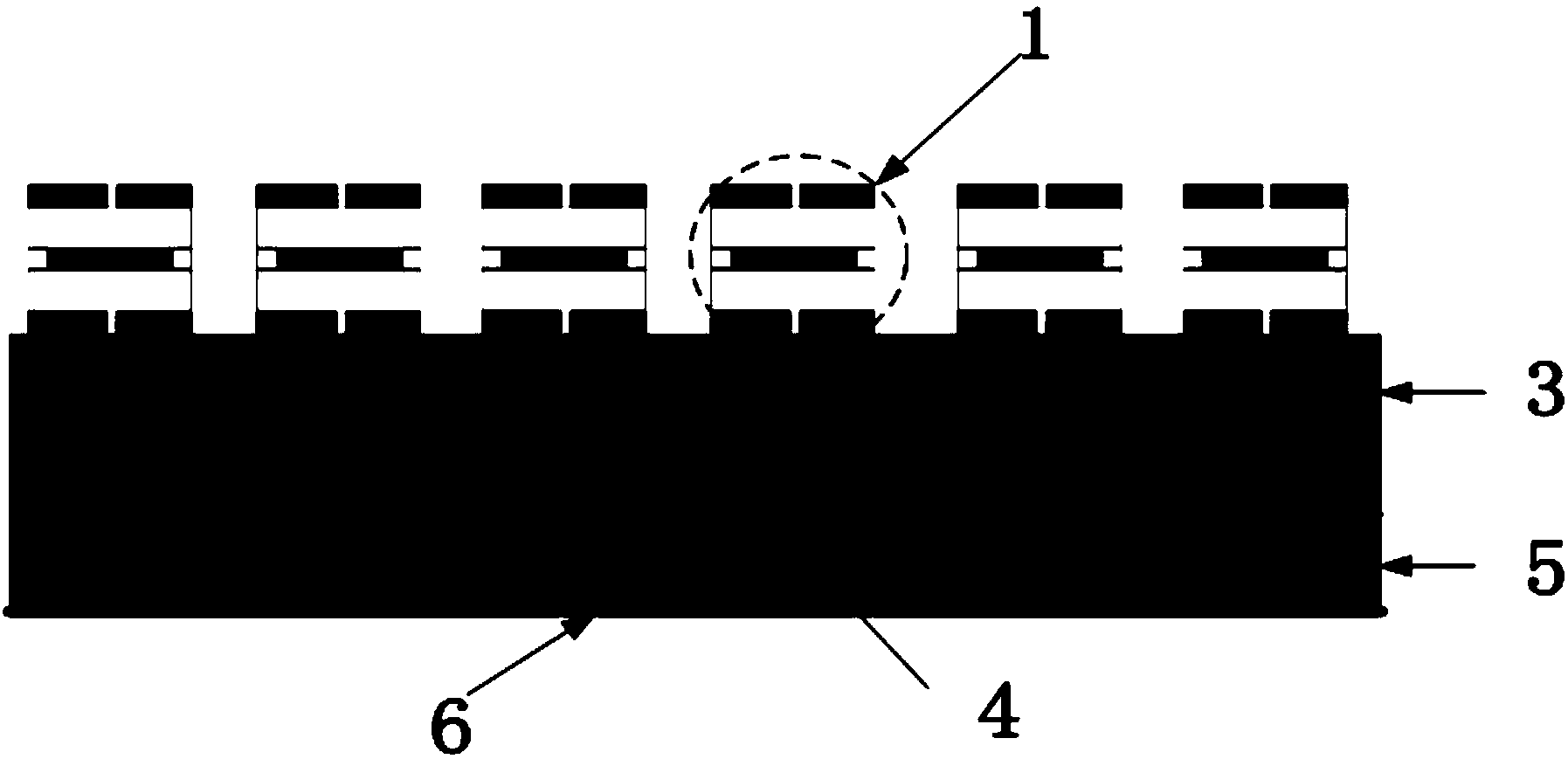
[0019] Such as figure 1 with image 3 As shown, an all-solid-state plasma proximity coupling stealth antenna array includes a solid-state plasma antenna unit 2, an upper dielectric substrate 3, a microstrip coupling feeder 4, a bottom dielectric substrate 5, and a grounded metal plate 6;

[0020] Such as figure 2 As shown, the solid-state plasma antenna unit 2 includes a semiconductor plasma unit 1, a plasma unit control chip 7, a row control line 8 and a column control line 9; wherein, as Figure 4 As shown, the semiconductor plasma unit 1 includes an insulating layer 10, a heavily doped P layer 12, a lowly doped I layer 11, a heavily doped N layer 13, and an insulating layer 10 from top to bottom, and an electrode is embedded in the middle of the insulating layer 10. 14; The heavily doped P layer 12, the lowly doped I layer 11 and the heavily doped N layer 13 are...


PUM


Abstract

The invention discloses an all solid-state plasma near coupling cloaking antenna array and a control method thereof. The all solid-state plasma near coupling cloaking antenna array comprises solid-state plasma antenna units, an upper layer dielectric substrate, a micro-strip coupling feeder line, a bottom layer dielectric substrate and a grounding metal plate. The solid-state plasma antenna units comprise semiconductor plasma units, plasma unit control chips, line control wires and queue control wires. All the plasma units are controlled independently through a peripheral control circuit, the plasma antenna units of different shapes are formed, and reconstruction of an antenna structure is achieved. The antenna structure is compact and simple, the cost is low, the antenna structure can work in a 1 GHz-100GHz wave band, the limitation that a traditional gas plasma antenna can not work in a high frequency band easily is broken through, and the advantages of being capable of achieving beam scanning, good in cloaking performance and the like are achieved.

Description

technical field [0001] The invention relates to the field of antenna and semiconductor technology, in particular to an all-solid-state plasma proximity coupling stealth antenna array. Background technique [0002] In modern high-tech warfare, radar systems and communication systems are crucial to the outcome of the war. As a key component of the radar system and communication system, the performance of the antenna has a crucial impact on the system; at the same time, due to the large radar cross section (RCS) of the antenna, it is also very easy to become a prominent target for the enemy to discover and attack. Therefore, it is of great significance to improve the performance index (including the stealth performance) of the antenna. [0003] For traditional antennas, in order to achieve the best transmission and reception effects, it is usually impossible to adopt conventional methods such as shape and coating of absorbing materials for stealth, so the RCS of the antenna is...

Claims


Application Information

Patent Timeline
Patent Type & Authority Applications(China)
IPC IPC(8): H01Q1/52H01Q21/00
Inventor 刘少斌周永刚陈鑫陈琳谢倩倩余志洋张博
Owner NANJING UNIV OF AERONAUTICS & ASTRONAUTICS
Learn More