DC-DC module power supply liquid cooling passage
A technology of liquid cooling channel and module power supply, which is applied in the field of electronics, can solve the problems of ignoring the influence of the heat dissipation effect of the module power supply, the overall heat dissipation effect cannot meet the requirements, and only consider the cooling liquid circulation flow, etc., to achieve simple structure, reliable welding, and resistance Reduced effect
- Summary
- Abstract
- Description
- Claims
- Application Information
AI Technical Summary
Problems solved by technology
Method used
Image

Examples
Embodiment Construction
[0025] The present invention will be further described below in conjunction with the accompanying drawings, but the protection scope of the present invention is not limited to the following description.
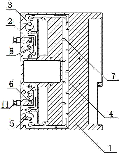
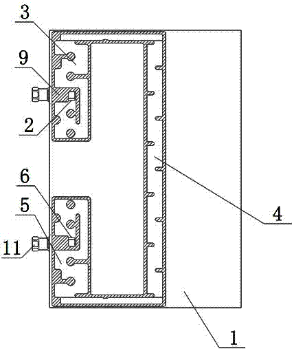
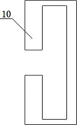
[0026] Such as figure 1 , figure 2 and image 3 As shown, the DC-DC module power supply liquid cooling channel includes a power supply housing 1, a liquid inlet 2, a channel body, a liquid outlet 6 and a cover plate 10. The power supply housing 1 is a plate structure, and the side wall of the power supply housing 1 is symmetrical. A liquid inlet 2 and a liquid outlet 6 are opened longitudinally, and the front of the power supply housing 1 is provided with a channel body from the liquid inlet 2 to the liquid outlet 6, and the channel body includes the front section 3 of the liquid cooling channel and the liquid cooling channel The middle section 4 and the rear section 5 of the liquid cooling channel, the two side walls of the front section 3 of the liquid cooling channel an...
PUM
 Abstract
Description
Claims
Application Information
PatSnap Eureka turns technology decisions into work you can execute. Powered by our Innovation Knowledge Graph, it runs expert workflows across engineering, life sciences, materials and intellectual property. Get your review-ready output in minutes.


