Switching-loss-free full-bridge non-isolated photovoltaic grid-connected inverter and on-off control timing sequence

A non-isolated, non-switching technology, applied in photovoltaic power generation, AC power input conversion to DC power output, output power conversion devices, etc., can solve problems such as diode reverse recovery, to eliminate leakage current and reverse recovery problem effect

Active Publication Date: 2014-12-24
SOUTHEAST UNIV
View PDF4 Cites 16 Cited by
  • Summary
  • Abstract
  • Description
  • Claims
  • Application Information

AI Technical Summary

Problems solved by technology

[0005] In addition, the turn-on process of the high-frequency main switch is still a hard switch, the turn-off process of the high-frequency auxiliary switch is also a hard switch, and the diode of the low-frequency reversing switch unit still has a reverse recovery problem

Method used


Image

  • Switching-loss-free full-bridge non-isolated photovoltaic grid-connected inverter and on-off control timing sequence
  • Switching-loss-free full-bridge non-isolated photovoltaic grid-connected inverter and on-off control timing sequence
  • Switching-loss-free full-bridge non-isolated photovoltaic grid-connected inverter and on-off control timing sequence

Examples


Embodiment 1

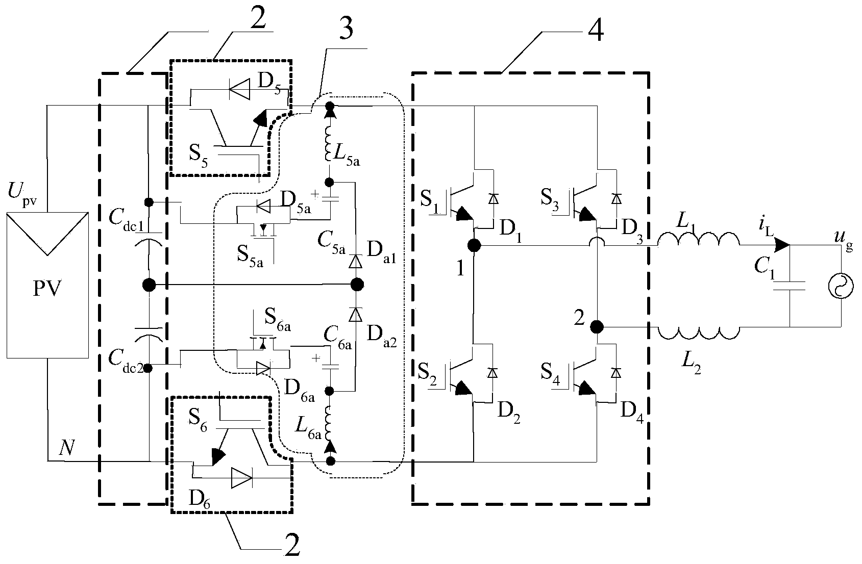
[0034] Such as figure 2 As shown, the configuration of the main circuit in Embodiment 1 of the present invention consists of the first voltage dividing capacitor C dc1 and the second divider capacitor C dc2 Form the basic unit 1;

[0035] By the fifth power switch tube S 5 and the fifth power diode D 5 Parallel combination, the sixth power switch tube S 6 and the sixth power diode D 6 Parallel combination forms the basic unit 2;

[0036] By the fifth auxiliary power switch S 5a and the fifth auxiliary power diode D 5a Parallel combination, the fifth auxiliary resonant inductor L 5a , the fifth auxiliary resonant capacitor C 5a , the sixth auxiliary power switch tube S 6a and the sixth auxiliary power diode D 6a Parallel combination, the sixth auxiliary resonant inductor L 6a , the sixth auxiliary resonant capacitor C 6a and the first auxiliary freewheeling clamp power diode D a1 , The second auxiliary freewheeling clamp power diode D a2 Form the basic unit 3; ...

Embodiment 2

[0044] Such as Figure 7 As shown, the main circuit of the second embodiment of the present invention consists of a DC filter capacitor C dc Composing the basic unit 71;

[0045] By the fifth power switch tube S 5 and the fifth power diode D 5 Parallel combination, the sixth power switch tube S 6 and the sixth power diode D 6 Parallel combination forms the basic unit 72;

[0046] By the fifth auxiliary power switch S 5a and the fifth auxiliary power diode D 5a Parallel combination, the fifth auxiliary resonant inductor L 5a , the fifth auxiliary resonant capacitor C 5a , the sixth auxiliary power switch tube S 6a and the sixth auxiliary power diode D 6a Parallel combination, the sixth auxiliary resonant inductor L 6a , the sixth auxiliary resonant capacitor C 6a and the first auxiliary freewheeling power diode D a1 Composing the basic unit 73;

[0047] By the first power switch tube S 1 and the first power diode D 1 Parallel combination, the second power switch...

Embodiment 3

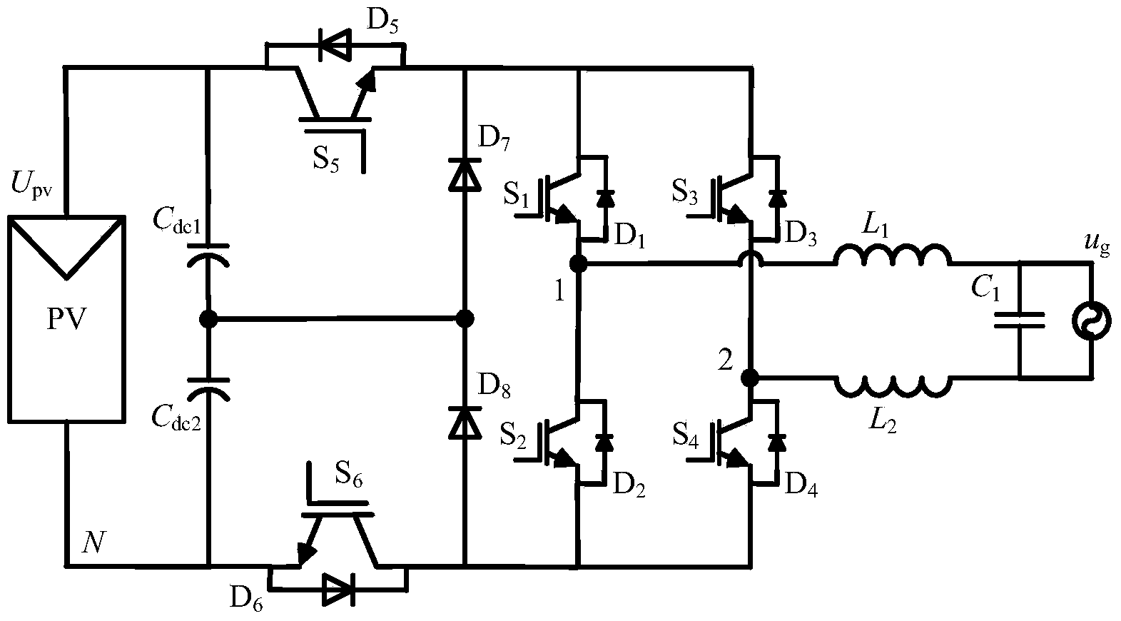
[0051] Such as Figure 8 As shown, the main circuit of the third embodiment of the present invention consists of the first voltage dividing capacitor C dc1 and the second divider capacitor C dc2 Composing the basic unit 81;

[0052] By the fifth power switch tube S 5 and the fifth power diode D 5 Parallel combination, the sixth power switch tube S 6 and the sixth power diode D 6 Parallel combination forms basic unit 82;

[0053] By the fifth auxiliary power switch S 5a and the fifth auxiliary power diode D 5a Parallel combination, the fifth auxiliary resonant inductor L 5a , the fifth auxiliary resonant capacitor C 5a , the sixth auxiliary power switch tube S 6a and the sixth auxiliary power diode D 6a Parallel combination, the sixth auxiliary resonant inductor L 6a , the sixth auxiliary resonant capacitor C 6a and the first auxiliary freewheeling power diode D a1 Composing the basic unit 83;

[0054] clamped by the seventh power diode D 7 and the eighth clampi...


PUM


Abstract

The invention discloses a switching-loss-free full-bridge non-isolated photovoltaic grid-connected inverter and an on-off control timing sequence. The inverter comprises a voltage division capacitance branch, a high-frequency main switching unit, a resonant network and a low-frequency change-over switch unit. Two sets of zero-current switching branches composed of the resonant network composed of full control switches, resonant capacitors and resonant inductors and auxiliary follow current clamping diodes are added, the on-off control timing sequence is matched, the zero-current turning-on and zero-current turning-off conditions of a fifth power switch tube S5 and a sixth power switch tube S6 can be achieved, the zero-current turning-on and zero-current turning-off conditions of a fifth auxiliary power switch tube Sa5 and a sixth auxiliary power switch tube Sa6 can be achieved, the reverse restoration of low-frequency change-over switch unit diodes D1-D4 can be eliminated, it is guaranteed that the common-mode voltage of the inverter is constantly one second of a battery voltage in the power transmission process, the resonance period and the follow current stage to eliminate leak currents, and therefore high frequency and minimization of the non-isolated photovoltaic grid-connected inverter can be achieved.

Description

technical field [0001] The invention relates to the technical field of high-efficiency grid-connected inverter topology, in particular to a full-bridge non-isolated photovoltaic grid-connected inverter without switching loss. Background technique [0002] The non-isolated photovoltaic grid-connected inverter has a simple circuit structure and high conversion efficiency and has been widely used in the industry. Such as figure 1 As shown, the existing technologies all work in the hard switching mode, and the ideal efficiency can only be achieved by operating at a relatively low switching frequency (10-20kHz), and relatively large filter inductors and filter capacitors are required, which increases and The volume weight of the grid inverter increases the cost. [0003] After research, it is found that the main factor limiting the increase of switching frequency of non-isolated grid-connected inverters is the switching loss of high-frequency switches. With the increase of swit...

Claims


Application Information

Patent Timeline
Patent Type & Authority Applications(China)
IPC IPC(8): H02M7/5387
CPCY02E10/56
Inventor 肖华锋
Owner SOUTHEAST UNIV
Why Eureka
Try Eureka