
Pushing mechanism

A technology of pushing mechanism and head, which is applied in the direction of garbage conveying, loading/unloading, garbage collection, etc. It can solve the problems of poor economical efficiency of transshipment, poor environmental protection of transshipment, and low utilization rate of garbage station space.

Active Publication Date: 2014-12-31
ZOOMLION ENVIRONMENTAL IND CO LTD
View PDF6 Cites 8 Cited by
  • Summary
  • Abstract
  • Description
  • Claims
  • Application Information

AI Technical Summary

Problems solved by technology

[0007] (1) The transfer economy is poor: the garbage bin and the supporting pull-arm garbage transfer vehicle are heavy, and the net load rate is low
[0008] (2) Poor adaptability, it is difficult to unload garbage bins in frozen areas and with large rebound;
[0009] (3) Poor environmental protection of transshipment: the problem of sewage leakage from the discharge door at the end of the garbage bin is difficult to control;
[0013] (3) Under high compression force, the compression stability of single oil cylinder is poor, which limits the volume of pre-compressed garbage blocks and cannot meet the requirements of a 31-ton transfer vehicle for one-time briquette loading
[0020] (1) The space utilization rate of the garbage station is low: the installation area of ​​the unloading push plate accounts for more than 50% of the total length of the unloading chute, which occupies a large area, the effective unloading length is short, and the space is small;
[0021] (2) Poor adaptability: Generally, one discharge position is set in the unloading trough area. When two or more discharge positions are set, the oil unloading stroke is large, the diameter of the oil cylinder is large, the cost is high, and the technical feasibility is poor;
[0022] (3) Unloading is discontinuous;
[0024] (1) Poor impact resistance when there is garbage unloading;
[0025] (2) Defects such as sewage leakage at the bottom and high cost
[0027] (1) There are obvious defects such as sewage leakage at the bottom and high cost;

Method used


Image

  • Pushing mechanism
  • Pushing mechanism
  • Pushing mechanism

Examples


Embodiment Construction

[0069] Specific embodiments of the present invention will be described in detail below in conjunction with the accompanying drawings. It should be understood that the specific embodiments described here are only used to illustrate and explain the present invention, not to limit the present invention.

[0070] In the present invention, under the situation of not stating to the contrary, the orientation words used such as "up, down, height direction, length direction" are usually under the normal use situation of the garbage compressor provided by the invention and the garbage unloading equipment. Defined, and in the present invention, the direction of movement of garbage is defined as "moving from back to front", specifically refer to figure 1 , Figure 4 , Image 6 , Figure 11 with Figure 14 Therefore, the "longitudinal direction" and the "front-rear direction" are the same, and both are the "left-right direction" in the above-mentioned direction of the drawing. The "he...


PUM


Abstract

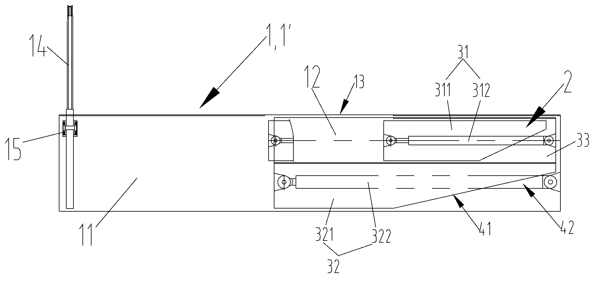
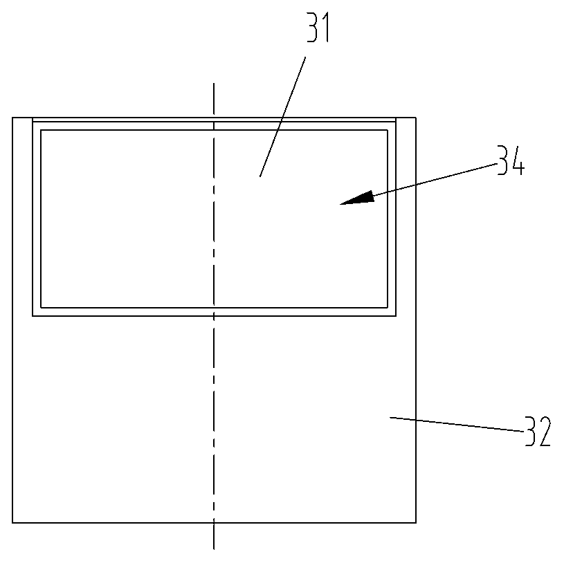
The invention discloses a pushing mechanism. The pushing mechanism is arranged on a substrate, and comprises a first pushing head assembly and a second pushing head assembly which is at least partially arranged below the first pushing head assembly; the first pushing head assembly and the second pushing head assembly can extend and retract along forward and backward directions respectively; when the two pushing head assemblies retract to retraction states, the pushing end of the first pushing head assembly and the pushing end of the second pushing head assembly are spaced in the extending and retracting direction of the first pushing head assembly, thereby forming a feeding region above the second pushing head assembly to receive materials to be pushed. By adopting the pushing mechanism, pushing operation such as laminated compression of trash and continuous unloading of trash can be finished through respective extension and retraction of the pushing head assemblies, the feeding region is designed skillfully, and the working stroke of at least a single pushing head assembly can be reduced, so that compacting effect of trash and / or the unloading efficiency of trash can be improved or increased through small-specification pushing head assemblies, the structural arrangement of a corresponding substrate can be optimized, and the practicability and economical efficiency are improved and increased.

Description

technical field [0001] The invention relates to the field of pushing garbage, in particular to a pushing mechanism. Background technique [0002] With the rapid development of urbanization, how to dispose of urban domestic and industrial waste is also a difficult problem to be solved in this field. Among them, in the treatment methods such as garbage transfer and landfill, it is necessary to compress the garbage into blocks before being transported away by the garbage transfer vehicle and processed. In the field of garbage compression, there are usually two kinds of equipment involved, one is the garbage compressor mainly responsible for garbage compression, and the other is the garbage unloading equipment mainly responsible for unloading garbage into the garbage compressor, which can usually be called the garbage collector. Unloading chute. The two devices in the prior art will be introduced one by one below. [0003] First of all, in the prior art, garbage compressors c...

Claims


Application Information

Patent Timeline
IPC IPC(8): B65F9/00
Inventor 魏剑锋
Owner ZOOMLION ENVIRONMENTAL IND CO LTD
Learn More