Tandem continuous ball mill and ball milling method

A continuous ball milling and tandem technology, used in grain processing and other directions, can solve the problems of low ball milling output, poor adjustability, and low production efficiency, and achieve the effect of improving work efficiency and grinding effect, improving overall pressure and improving grinding efficiency.

Active Publication Date: 2015-01-07
GUANGDONG EDING IND
View PDF7 Cites 22 Cited by
  • Summary
  • Abstract
  • Description
  • Claims
  • Application Information

AI Technical Summary

Problems solved by technology

The utility model overcomes the defects of the existing ceramic ball milling equipment, such as large and complicated structure, low production efficiency, unstable product quality and poor adjustability
The problems existing in this utility model are as follows: the overflow method is used to discharge the material, and the slurry overflows from the discharge end and also overflows from the feed end at the same time; the output of the first stage ball mill is low, which cannot meet the production capacity of the ball mill tank behind; it cannot be realized Add materials and grinding ball media to the working chamber at the back regularly and quantitatively without stopping the machine

Method used


Image

  • Tandem continuous ball mill and ball milling method
  • Tandem continuous ball mill and ball milling method
  • Tandem continuous ball mill and ball milling method

Examples


Embodiment 1

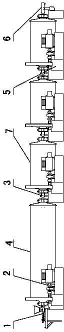
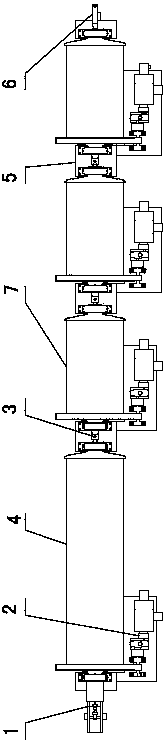
[0040] Such as figure 1 , 2 As shown: the feeding device 1 is an independent transmission unit, which is at the forefront of the entire tandem continuous ball mill. The first-stage ball mill tank 4 and the independent transmission device 2 form a first-stage ball mill unit with independent transmission. The second-stage ball mill tank 7 and the independent The transmission device 2 constitutes a two-stage ball mill unit with independent transmission. The feeding device delivery cylinder 107 is inserted into the feed end cover of the primary ball mill tank 4 of the ball mill. The primary ball mill tank 4 and the adjacent secondary ball mill tank 7 They are connected through the connection device 3, the secondary ball milling tank has three stages, and the adjacent secondary ball milling tanks 7 are connected through the connection device 3, and the connection device 3 is responsible for supplying the secondary ball milling tank 7 without stopping the machine. Add grinding ball...

Embodiment 2

[0058] When the particle size of the material is relatively low, you can choose to connect two secondary ball milling pots 7 behind the primary ball milling pot 4. The length of the primary ball milling pot 4 is 15m, and the length of the secondary ball milling pot 7 is 5m. The structure remains unchanged, and the assembly method and ball milling method are as in Example 1.

Embodiment 3

[0060] If the material requirements are high, you can choose to connect multiple secondary ball milling pots 7 behind the primary ball milling pot 4. The specific number of stages is selected according to actual needs. It is 8m, and the other structural shapes are unchanged, and the assembly method and ball milling method are as in Example 1.


PUM


Abstract

The invention discloses a tandem continuous ball mill and a ball milling method and belongs to the technical field of equipment for producing ceramic products and ball milling technologies. A feeding device (1) is communicated with a feeding end of a first-stage ball milling tank (4), wherein a plurality of second-stage ball milling tanks (7) are connected in series; the length of the first-stage ball milling tank (4) is 1.5-3 times that of one second-stage ball milling tank (7); an inner cavity of the first-stage ball milling tank (4) has a taper of which the diameter is gradually reduced from the feeding end to the discharging end. The tandem continuous ball mill can be used for materials with different sizes; the discharging mode is changed from the traditional overflow into flow extraction; in the ball milling method, materials with different particle sizes are pertinently added; after materials of which the particle sizes are 0.5-15mm are pulped, the pulped materials are directly added in each second-stage ball milling tank (7) through a connecting device (3); after materials of which the particle sizes are 0.1-0.5mm are pulped, the pulped materials are directly added in the tail-end second-stage ball milling tanks (7) through the connecting devices (3), so that the grinding efficiency is greatly improved.

Description

technical field [0001] The invention relates to a serial continuous ball mill and a ball milling method, which belong to the technical field of ceramic product production equipment and ball milling technology. It can also be used for ball milling of other clay products that require ball milling. Background technique [0002] Continuous ball mills currently used in the market are generally monomer continuous mills and multi-section serial continuous ball mills. The purpose of continuous ball mills is to increase production, and to increase the production of continuous ball mills under the same ore particle size requirements. The commonly used method is to lengthen and enlarge For the ball milling tank, due to the horizontality of the material and the flow direction of the material, when the ball milling tank is too long, there will be a problem of more grinding ball media at one end and less at the other end, and at the same time, there will be a problem of mixed size particl...

Claims


Application Information

Patent Timeline
Patent Type & Authority Applications(China)
IPC IPC(8): B02C17/10B02C17/18B02C17/22B02C23/10
CPCB02C17/10B02C17/183B02C17/184B02C17/22
Inventor 肖凤军
Owner GUANGDONG EDING IND
Why Eureka
Try Eureka