Magnetic mud separation system of cutting equipment and separation method

A technology of cutting equipment and separation system, which is applied in magnetic mud separation system and the field of magnetic mud separation of cutting equipment, which can solve the problems of the decrease of cutting efficiency and cutting quality, failure to circulate to magnetic mud separator, uneven distribution of oil sand liquid purity, etc. problems, to achieve the effect of improving cutting efficiency, compact structure and improving cutting quality

Inactive Publication Date: 2015-01-07
TAIZHUO SHUANGHUI MACHINERY EQUIP
View PDF6 Cites 4 Cited by
  • Summary
  • Abstract
  • Description
  • Claims
  • Application Information

AI Technical Summary

Problems solved by technology

The cutting and magnetic mud separation steps of the current cutting equipment are separated. When the timing separation measures are adopted, there are still some magnetic mud and impurities in the oil sand liquid. During the period from each separation to the next separation, the recycled The concentration and composition of the oil sand liquid in the oil sand liquid are constantly changing, which reduces the cutting efficiency and cutting quality; when adopting the unified treatment measures after storage first, the oil sand liquid used every time is stored first, and then used after being processed. The corundum and magnetic mud in the oil sand liquid will deposit during standing, and cannot be circulated to the magnetic mud separator. The deposited corundum will reduce the carborundum content in the oil sand liquid, reduce the quality of the oil sand liquid, and affect the cutting equipment At the same time, the corundum in the pure oil sand liquid will also deposit when it is left standing after magnetic mud separation, and the purity distribution of the oil sand liquid is uneven, which further reduces the quality of the oil sand liquid and further affects the cutting equipment. cutting; such a cycle leads to a decrease in the service life of the oil sand fluid
Furthermore, since the oil sand liquid needs to be stored in the middle of the cutting and magnetic mud separation steps, the required amount of oil sand liquid is very large to meet the production demand, which increases the production cost; and most of the oil sand liquid is in a waiting state , making the use of oil sand fluid inefficient
Furthermore, the current entire system structure is huge and not compact, and occupies a large area of ​​the factory building, which virtually increases the production cost

Method used


Image

  • Magnetic mud separation system of cutting equipment and separation method
  • Magnetic mud separation system of cutting equipment and separation method
  • Magnetic mud separation system of cutting equipment and separation method

Examples


Embodiment Construction

[0028] The following are specific embodiments of the present invention and in conjunction with the accompanying drawings, the technical solutions of the present invention are further described, but the present invention is not limited to these embodiments.

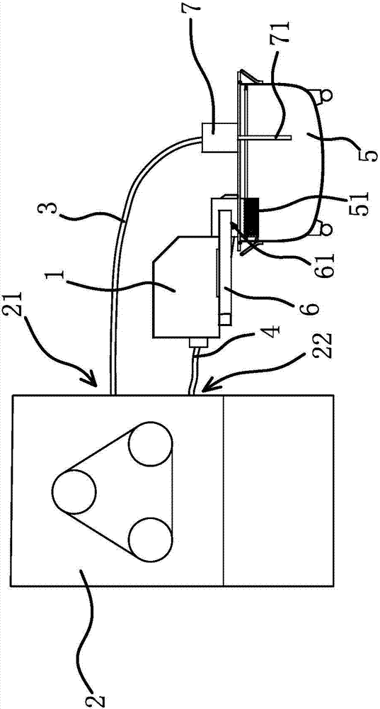
[0029] A magnetic mud separation system for cutting equipment, such as figure 1 As shown, the magnetic mud separation system includes a liquid inlet pipe 3, a liquid discharge pipe 4, a magnetic separator 1, and an oil sand bucket 5. The cutting device 2 is provided with an oil sand inlet 21 and an oil sand outlet 22. The inlet of the magnetic separator 1 is The liquid port 11c communicates with the oil sand outlet 22 on the cutting device 2 through the drain pipe 4, the liquid inlet 11c of the magnetic separator 1 is located below the oil sand outlet 22, and the oil sand barrel 5 is arranged below the magnetic separator 1. The liquid guide box 6 is fixed on the magnetic separator 1, the liquid outlet 11d of the magnetic s...


PUM


Abstract

The invention provides a magnetic mud separation system of cutting equipment and a separation method, belongs to the operation field, and solves the technical problems that the existing cutting equipment is low in oil sand liquid use efficiency and short in service life. The magnetic mud separation system of the cutting equipment comprises a liquid inlet pipe, a liquid discharge pipe and a magnetic separator, wherein an oil sand inlet and an oil sand outlet are formed in the cutting equipment, the liquid inlet of the magnetic separator is communicated with the oil sand outlet in the cutting equipment through the liquid discharge pipe, the liquid outlet of the magnetic separator is communicated with the sand oil inlet in the cutting equipment through the liquid inlet pipe, and a delivery pump sending the oil sand liquid into the oil sand inlet through the liquid inlet pipe is arranged between the liquid outlet of the magnetic and the liquid inlet pipe. The magnetic mud separation system has the advantages of always keeping the quality of the oil sand liquid. The magnetic mud separation method has the advantage that the oil sand liquid separated from magnetic mud immediately circulates to the cutting equipment, so that the use efficiency of the oil sand liquid is improved.

Description

technical field [0001] The invention belongs to the field of work, and relates to a magnetic mud separation system for cutting equipment; the invention also relates to a magnetic mud separation method for cutting equipment, which belongs to the field of work. Background technique [0002] Some of the existing cutting equipment use oil-sand liquid for cutting, such as multi-wire cutting machines, etc. The oil-sand liquid contains emery, and the workpiece is cut by emery grinding. Mud or powdered iron-like cuttings impurities will be mixed with the oil sand liquid, and the composition of the mixed oil sand liquid will change, resulting in a decrease in cutting efficiency and unstable surface quality of the cut workpiece, until the workpiece cannot be cut. [0003] In order to save the oil sand liquid and protect the environment, the oil sand liquid is currently recycled. By removing the magnetic mud in the oil sand liquid, the purity of the oil sand liquid can be restored to t...

Claims


Application Information

Patent Timeline
Patent Type & Authority Applications(China)
IPC IPC(8): B03C1/30B03C1/02B28D7/00
Inventor 王敏金建华蔡文辉唐兆勇叶坤
Owner TAIZHUO SHUANGHUI MACHINERY EQUIP
Why Eureka
Try Eureka