Large bar hydraulic shear front hydraulic automatic guide device
An automatic guiding and hydraulic shearing technology, which is applied in guiding/positioning/alignment devices, shearing devices, attachments of shearing machines, etc., can solve the problem of affecting the production rhythm of the rolling line, affecting the biting of the continuous rolling mill, and the bending of the billet head and tail and other problems, to achieve the effect of convenient disassembly, assembly, maintenance and replacement, reduction of production costs and energy consumption, and faster rolling rhythm
- Summary
- Abstract
- Description
- Claims
- Application Information
AI Technical Summary
Problems solved by technology
Method used
Image
Examples
Embodiment 1
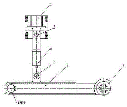
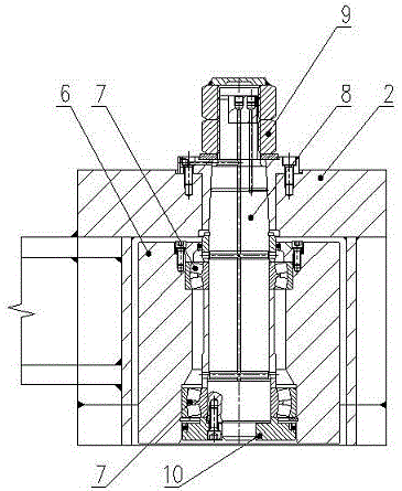
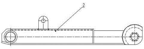
[0022] Example 1: Such as figure 1 — Image 6 , a hydraulic automatic guide device before hydraulic shearing of large bars, comprising a rotating guide wheel mechanism 1, a guide arm 2, a hydraulic cylinder 3, and a hydraulic cylinder base 4, the rotating guide wheel mechanism 1 and the guide arm 2 are assembled together, the The guide arm 2 is connected with the hydraulic cylinder 3 and the hydraulic cylinder 3 and the hydraulic cylinder base 4 through the movable connection structure 5, and the rotating guide wheel mechanism 1 includes a guide wheel 6, a self-aligning roller bearing 7, and a guide wheel. Axle 8, lock nut 9 and end cover 10, the self-aligning roller bearing 7 is located between the guide wheel 6 and the guide wheel shaft 8, the end cover 10 is sleeved on one end of the guide wheel shaft 8, the guide wheel shaft 8 The other end is connected with a lock nut 9, the guide arm 2 is located between the guide wheel 6 and the lock nut 9, the movable connection str...
Embodiment 2
[0023] Example 2: Such as figure 1 — Image 6 , as an improvement of the present invention, the number of the spherical roller bearings 7 is two, which are installed at both ends of the guide wheel 6 respectively. Thereby ensure that the force of the guide wheel 6 is balanced and prolong its service life. The rest of the structures and advantages are exactly the same as in Embodiment 1.
Embodiment 3
[0024] Example 3: Such as figure 1 — Image 6 , as an improvement of the present invention, the stroke of the hydraulic cylinder 3 is controlled by a stroke switch installed next to the driving hydraulic cylinder. According to the size of the intermediate billet, it is only necessary to manually adjust the position of the stroke switch that controls the stroke of the hydraulic cylinder before production. During the working process, the stroke switch will feed back the detected signal to the solenoid valve on the hydraulic valve table for automatic control. The stroke of the hydraulic cylinder. The rest of the structures and advantages are exactly the same as in Embodiment 1.
PUM
 Abstract
Description
Claims
Application Information
 - R&D
- Intellectual Property
- Life Sciences
- Materials
- Tech Scout
- Unparalleled Data Quality
- Higher Quality Content
- 60% Fewer Hallucinations
Browse by: Latest US Patents, China's latest patents, Technical Efficacy Thesaurus, Application Domain, Technology Topic, Popular Technical Reports.
© 2025 PatSnap. All rights reserved.Legal|Privacy policy|Modern Slavery Act Transparency Statement|Sitemap|About US| Contact US: help@patsnap.com


