
In-Line Cutting or Marking System for Rotating Laser Masks in Ring Ribbon

A mask and ribbon technology, applied in the field of laser cutting and engraving, can solve the problems of pattern deformation, inaccessibility of laser technology, restricting the increase of equipment productivity, etc., to eliminate the deformation of cutting or engraving patterns, improve the speed of laser cutting and engraving, The effect of simplifying drive control requirements

Inactive Publication Date: 2015-10-21
汤振华
View PDF5 Cites 0 Cited by
  • Summary
  • Abstract
  • Description
  • Claims
  • Application Information

AI Technical Summary

Problems solved by technology

This type of equipment also has similar defects to existing cutting equipment. If high-precision pattern marking is to be carried out on the surface of the material under the condition of high-speed movement of the material, the pattern will be deformed due to the speed matching problem, causing quality problems and causing the product to be scrapped; and The complexity of the engraved pattern directly affects the engraving speed. Within the same range, the more complex the pattern, the longer the engraving time, which requires the longer the material to be engraved stays in the scanning range of the galvanometer, that is, the need to reduce the material transmission. Speed, which directly affects production efficiency
[0004]Due to the above defects, the application of laser cutting and marking in industrial production is limited. Faced with the continuous improvement of equipment capabilities, the application of laser in industrial production It may become a bottleneck that hinders the improvement of equipment production capacity
And some fields that used other methods for cutting or marking, because of the above reasons, the laser technology cannot enter, and the advantages of high resolution and environmental friendliness of laser marking cannot be brought into play.

Method used

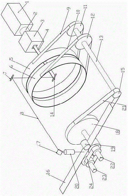

Image

  • In-Line Cutting or Marking System for Rotating Laser Masks in Ring Ribbon
  • In-Line Cutting or Marking System for Rotating Laser Masks in Ring Ribbon
  • In-Line Cutting or Marking System for Rotating Laser Masks in Ring Ribbon

Examples


Embodiment 1

[0037] Example 1: Cutting or marking system for cylindrical rotary mask

[0038] see figure 1, This embodiment consists of a laser unit, two cylindrical masks arranged side by side coaxially, the first mask 5, the second mask 6, an optical path assembly, and a drive and transmission unit.

[0039] The laser unit includes a laser light source 1 , a light source interface 2 and a laser beam expansion and shaping unit 3 . The laser light source can be YAG or CO2 laser source, and its intensity can be selected according to the material properties, thickness, transmission speed and other parameters of the material to be processed. The laser light source can continuously adjust the intensity during operation, and the external trigger laser emission or shutdown. The emitting end of the laser light source 1 has a threaded bayonet threaded connection with the light source interface 2, and the other end of the light source interface 2 is connected with the laser beam expanding and shap...

Embodiment 2

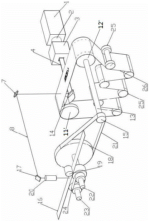
[0048] Embodiment 2: An on-line cutting or marking system for an annular belt-shaped rotatable laser mask.

[0049] see figure 2 , This embodiment is composed of a laser part, a tape mask 26, an optical path assembly, and a driving and transmission part. The structure of the laser part and the optical path assembly is the same as that of Embodiment 1. The structural arrangement relationship of the transmission components at the processing end is also the same as that of Embodiment 1. The transmission mechanism includes the first mask end synchronous pulley 11', the second mask end synchronous pulley 12', six middle mask transmission wheels 25, the transmission shaft 13, the first processing end synchronous pulley 18, the second processing End synchronous pulley 15, first processing end synchronous belt 21, first processing end transmission shaft 22, second processing end transmission shaft 23 arranged in parallel, first processing end transmission shaft 22 or second process...


PUM


Abstract

The invention discloses an annular banded rotating laser mask online cutting or engraving system. The annular banded rotating laser mask online cutting or engraving system comprises a laser portion which provides a continuous laser water source with adjustable output energy, a mask, a light path assembly and a driving and transmission portion; the mask which allows high-speed rotation and circulating rotation provides needed patterns or cut or engraved pattern sizes; the light path assembly cuts pattern information on the mask or engraves the pattern information on the mask to to-be-machined materials; the driving and transmission portion provides a power source and enables movement and speed between the mask and the to-be-machined materials to be matched to achieve synchronous transmission. The annular banded rotating laser mask online cutting or engraving system has the advantages of avoiding movement of the light path assembly, eliminating cutting and engraving speed limit caused by mass inertia of the light path assembly, achieving an effect of improving the laser cutting and engraving speed, eliminating the defects that, in the prior art, the light path assembly movement speed has a limit and accordingly the integral machining speed is limited and cutting or engraved patterns deform under movement states of to-be-machined materials, effectively improving the production efficiency, reducing maintenance costs and being wide in applicable range.

Description

technical field [0001] The invention relates to a method and system for online cutting or marking of materials by a rotatable laser mask, belonging to the field of laser cutting and marking. Background technique [0002] At present, in the field of laser cutting, the material to be cut is generally in a static state, and the laser focusing lens is driven by an electric servo mechanism to move in two axial directions on a plane perpendicular to the material to be cut, so that the laser can cut all the Required pattern (pattern refers to continuous or discontinuous lines or curves, and graphics or symbols composed of characters, etc., which can be a combination or superposition of lines, curves or characters, or graphics composed of a single element). If the material to be cut must be kept in motion according to the process requirements, that is, it is applied to continuous materials or the material needs to be continuously conveyed due to the production process requirements, ...

Claims


Application Information

Patent Timeline
Patent Type & Authority Patents(China)
IPC IPC(8): B23K26/38B23K26/362B23K26/70
CPCB23K26/0643B23K26/38
Inventor 汤振华
Owner 汤振华
Learn More