
Ultraviolet photoelectric sensor positioning fixture and mounting method thereof

A positioning fixture and electric sensor technology, applied in the field of ultraviolet flame detection, can solve the problems of affecting the assembly progress, size cannot be guaranteed, outflow phenomenon, etc., and achieve the effect of improving assembly efficiency, good working condition, and saving work flow

Active Publication Date: 2015-01-07
SHAANXI AVIATION ELECTRICAL
View PDF7 Cites 2 Cited by
  • Summary
  • Abstract
  • Description
  • Claims
  • Application Information

AI Technical Summary

Problems solved by technology

When assembling, GD414 one-component vulcanized silicone rubber is filled and Nanda 704 silicone rubber is filled with outflow phenomenon, and the dosage cannot be determined; at the same time, when the silicone rubber is outflowed, follow-up cleaning is required, and the excess silicone rubber is not easy to clean and will appear. Debris is difficult to clean up, etc.
Vulcanized silicone rubber vulcanization cycle at room temperature is slow, which affects the assembly progress
There are many human factors brought about by the manual assembly process, and the size cannot be guaranteed. The out-of-tolerance rate of one-time assembly exceeds 60%, and the ultraviolet photoelectric tube will be tilted, and the received optical signal refracted by the double spherical surface will be weakened, resulting in the photoelectric effect. Engine combustion chamber flame test

Method used


Image

  • Ultraviolet photoelectric sensor positioning fixture and mounting method thereof
  • Ultraviolet photoelectric sensor positioning fixture and mounting method thereof
  • Ultraviolet photoelectric sensor positioning fixture and mounting method thereof

Examples


Embodiment Construction

[0022] Describe the present invention below in conjunction with specific embodiment:

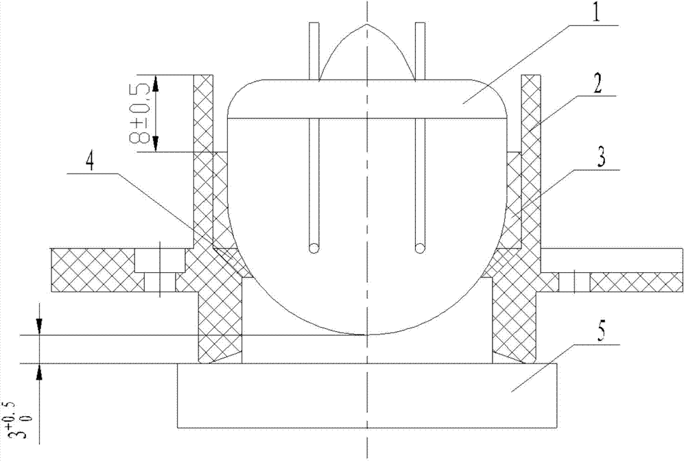
[0023] The ultraviolet flame detection technology can detect the invisible ultraviolet light with a wavelength of 180nm ~ 290nm produced by the combustion chamber of the aero-engine. Its gas-filled UV photocell acts as a sensitive element that detects invisible UV radiation.

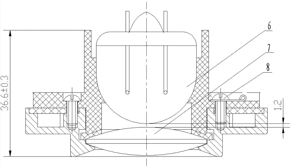
[0024] The working principle of the ultraviolet photoelectric cell assembly and the ultraviolet photoelectric sensor that needs to be assembled in this embodiment is: when the oil-air mixture in the engine combustion chamber is burned, ultraviolet radiation is generated, and after being focused by a quartz convex lens, it breaks down the gas in the sensitive medium ultraviolet photoelectric cell, and the ultraviolet radiation The photocell is turned on and outputs a voltage signal. Judging the flame combustion in the combustion chamber by the data segment of the output voltage signal, when the effective value of the o...


PUM


Abstract

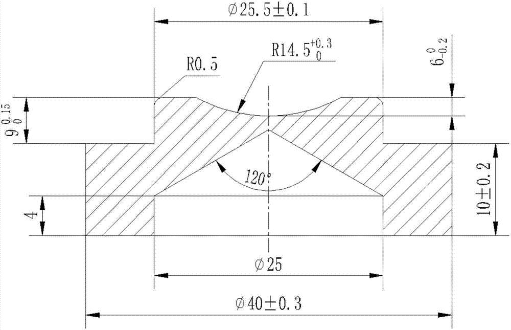
The invention provides an ultraviolet photoelectric sensor positioning fixture and a mounting method thereof. The positioning fixture is of a coaxial sectioned cylinder structure, the outer circumference of a small cylinder of an upper section of the positioning fixture is in clearance fit with the inner circumference of the lower end of a polytetrafluoroethylene lining, a spherical groove is formed in the end face of the small cylinder, the spherical center of the spherical groove is positioned in the central axis of the positioning fixture, the spherical radius of the small cylinder is equal to that of the bottom of an ultraviolet photoelectric tube, and the difference between the thickness of the small cylinder and the maximum depth of the spherical groove is equal to the assembly spacing between the bottom of the ultraviolet photoelectric tube required by the design of an ultraviolet photoelectric sensor and the bottom of the polytetrafluoroethylene lining. The positioning fixture serves as a tool, an ultraviolet flame detector can be effectively positioned, the gap and the dosage of one-component vulcanizing silicone rubber with bonding, fixing and shake-proof actions are effectively controlled, and cleaning after construction is omitted, process and standardization of assembly technology are ensured, and assembly efficiency is improved.

Description

technical field [0001] The invention belongs to the technical field of ultraviolet flame detection, and relates to a positioning fixture of an ultraviolet photoelectric sensor and an installation method thereof. Background technique [0002] At present, domestic aero-engines mainly use ion flame detectors. Compared with ion flame detectors, ultraviolet flame detectors have faster response speed, longer detection interval, better environmental adaptability and higher reliability. Research and development of ultraviolet flame detectors is the development trend in the field of ultraviolet flame detection. [0003] At present, the assembly method used for the ultraviolet photoelectric sensor in the ultraviolet flame detector has many manual processes, and the positioning of the assembly gap and the ultraviolet discharge tube cannot be realized, and the distance between the ultraviolet photoelectric tube and the polytetrafluoroethylene bushing cannot be effectively guaranteed. T...

Claims


Application Information

Patent Timeline
IPC IPC(8): B25B11/02F16B11/00
CPCB25B11/02F16B11/006
Inventor 杨江美党腾华李忠祥石元元
Owner SHAANXI AVIATION ELECTRICAL
Learn More