Visual experiment system device used for simulating grouting plugging for water inrush of roadways

A technology of test system and grouting system, which is applied in the field of visual indoor test system device, can solve problems such as concealment unpredictability and complexity of engineering geological problems, and achieve moderate space occupation, easy operation and adjustment, and simple structural design Effect

Inactive Publication Date: 2015-01-07
CHINA UNIV OF MINING & TECH
6 Cites 24 Cited by

AI-Extracted Technical Summary

Problems solved by technology

At present, grouting sealing technology has been used in roadway water inrush rescue and disaster relief projects at home and abroad to obtain some successful experience, but due to the complexity, concealment and unpredictability of engineering geological prob...

Abstract

The invention relates to a visual experiment system device used for simulating grouting plugging for water inrush of roadways. The visual experiment system device can be used for conducting visual grouting plugging test research based on indoor simulation of grouting plugging of roadways of different inclinations and curvatures on different water inrush pressure and flow rate conditions. The visual experiment system device comprises eight parts including a flowing water system, a roadway model system, a grouting system, a video and picture recording system, a flow monitoring system, a data acquisition system, a support system and a waste liquor collecting system. The flowing water system comprises a water source pipe, a header tank, a water drainage pipe, a water inrush pipeline, control valves and a water tank bracket; the roadway model system comprises a transparent pipeline and crushed aggregates; the grouting system comprises a high-pressure grouting machine, a grouting pipeline and a pressure gauge; the video and picture recording system comprises four digital cameras; the flow monitoring system comprises two flow totalizers; the data acquisition system comprises four pressure sensors and a DT data acquisition instrument; the support system comprises an expansion bracket, an expansion table and a scale; the waste liquor collecting system comprises a waste liquor pipe and a waste liquor barrel.

Application Domain

Technology Topic

Image

  • Visual experiment system device used for simulating grouting plugging for water inrush of roadways

Examples

  • Experimental program(1)

Example Embodiment

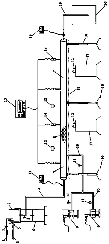
[0021] Such as figure 1 As shown, the present invention is implemented as follows: The visual test system device for simulating water inrush grouting and blocking of roadways of the present invention is composed of water moving system, roadway model system, grouting system, view recording system, flow monitoring System, data acquisition system, support system, waste liquid collection system are composed of 8 parts. The dynamic water system consists of (1) water source pipe, (2) water collection tank, (3) drain pipe, (4) water inrush pipeline, (5) control valve and (6) water tank bracket; (6) water tank bracket is made of steel plate material It is made to ensure the stability and safety of the whole part of the moving water system. It can freely adjust the lifting height, so that (2) the height of the water collection tank can be adjusted up and down, and different water inrush pressures can be simulated by the height of the water head; (1) One end of the water source pipe is connected to the outside The other end of the water source extends into (2) the water collection tank, and (5) a control valve is installed on it, which can adjust the water flow; (2) the top side of the water collection tank is lower and is provided with an overflow collection device, connected to (3) The drain pipe can drain (2) the overflowing water from the water collection tank in time to ensure the establishment of a stable water head; (4) One end of the water inrush pipeline is connected to (2) the lower end of the water collection tank, and (5) a control valve is installed on it. The flow rate is adjusted to simulate the test water inrush flow, and the water flow value can be displayed through the (13) flow totalizer connected at the other end. The roadway model system is composed of (7) transparent pipes and (8) scraps; (7) transparent pipes are used to simulate water inrush roadways, and can be replaced according to test needs; (8) scraps can be selected according to test needs. To simulate the gravel blocks, sand bags, etc. that were filled and thrown before grouting and plugging in the water inrush roadway. The grouting system consists of (9) high-pressure grouting machine, (10) grouting pipeline and (11) pressure gauge; according to the experimental design of single-liquid grouting or multi-liquid grouting selection (9) the number of high-pressure grouting machines, and Effectively connect with (10) grouting pipeline through a multi-way joint; (10) There are (11) pressure gauges installed on different positions of the grouting pipeline to observe the grouting pressure value, and the other end is connected to (7) transparent pipeline . The view recording system is composed of 4 (12) digital cameras distributed at different positions of the (7) transparent pipe at intervals, and its main function is to record test videos and take photos during the test. The flow monitoring system is composed of two (13) flow totalizers located at the front and back ends of the (7) transparent pipeline. Its main function is to display the water inrush flow, and to monitor the flow changes during the grouting and blocking process of the simulated water inrush roadway. The data acquisition system consists of 4 (14) pressure sensors connected at intervals (7) at different positions of the transparent pipeline and (15) DT data acquisition instrument for pressure change data acquisition and storage. Its main function is to collect and store simulated grouting (7) Pressure changes at different positions of the transparent pipe during the blocking test. The support system is composed of (16) telescopic frame, (17) telescopic table and (18) ruler; the position of 3 (16) telescopic frames used for erecting (7) transparent pipe can be moved and the height can be adjusted freely. The (18) ruler on it can adjust (7) the inclination and curvature of the transparent pipe; (17) the telescopic table is used to set up (12) the digital camera, and the height can be adjusted freely to adjust the (12) digital camera and (7) ) The distance of the transparent pipe, select the best view shooting position. The waste liquid collection system consists of (19) waste liquid pipe and (20) waste liquid bucket connected to the end of (7) transparent pipe. Its main function is to drain and store the aqueous solution during the test and part of the grouting slurry carried out. , To prevent direct discharge and pollution of water sources and the environment.
[0022] The (1) water source pipe, (3) drain pipe and (4) water inrush pipeline are all equipped with control valves to adjust the flow rate.
[0023] The (2) water collection tank is lower on one side and provided with an overflow collection device, which is connected with (3) the drain pipe.
[0024] The (6) water tank bracket can be raised and lowered freely, so that the height of the (2) water collection tank can be adjusted to reach the water head height required by the test.
[0025] The (7) transparent pipe is a large diameter (greater than 100mm) transparent pneumatic pipe, which realizes the visualization during the simulation grouting plugging test.
[0026] The (10) grouting pipeline is equipped with a multi-way joint and (11) a pressure gauge, so that the grouting pressure can be observed at any time.
[0027] The (13) flow totalizer has the function of displaying and storing instantaneous flow and accumulated flow data.
[0028] The combination of (15) DT data acquisition instrument and (14) pressure sensor has the function of collecting and storing pressure change data every set time interval.
[0029] The (16) telescopic frame is provided with a (18) ruler, and the height can be adjusted freely.
[0030] The visual test system device for simulating water inrush grouting and plugging of roadways of the present invention is a set of indoor experimental researches for simulating water inrush grouting and plugging in coal mine production units, universities and scientific research units, etc. Visual test system. It can simulate the visualization and test effect of grouting and blocking of roadways under different conditions of water inrush pressure and water inrush flow. It can also simulate the visualization and test effect of grouting and plugging in roadways with inclination and curvature during water inrush. Research to explore the grouting sealing effect and influencing factor criteria under different water inrush factors and roadway characteristics is of great significance for guiding water inrush in roadways encountered in actual underground engineering construction to adopt grouting to plug rescue and disaster relief projects. And value.

PUM

no PUM

Description & Claims & Application Information

We can also present the details of the Description, Claims and Application information to help users get a comprehensive understanding of the technical details of the patent, such as background art, summary of invention, brief description of drawings, description of embodiments, and other original content. On the other hand, users can also determine the specific scope of protection of the technology through the list of claims; as well as understand the changes in the life cycle of the technology with the presentation of the patent timeline. Login to view more.

Similar technology patents

Classification and recommendation of technical efficacy words

Why Eureka
Try Eureka