
rotary jet internal combustion engine

A technology of rotary jet and internal combustion engine, applied in the field of internal combustion engine and rotary jet internal combustion engine, can solve the problems of low thermal efficiency of internal combustion engine and narrow working speed range, and achieve the effects of high compression ratio, wide working speed range and high combustion efficiency

Inactive Publication Date: 2015-12-02
向兵
View PDF5 Cites 0 Cited by
  • Summary
  • Abstract
  • Description
  • Claims
  • Application Information

AI Technical Summary

Problems solved by technology

[0004] The object of the present invention is to provide a rotary jet internal combustion engine for the deficiencies in the prior art, compress the air (or the mixture of air and fuel) and store it in the air storage tank, the air storage tank and the rotary jet combustion chamber assembly Connected, the mixture of air and fuel is combusted in the rotary jet combustion chamber assembly, and the high-pressure gas generated by the combustion is ejected from the circumference of the combustion chamber along the tangential direction at high speed, and the relevant components are driven to rotate to do work, which solves the problem of low thermal efficiency and work problems of existing internal combustion engines. Narrow speed range and other problems, it has the characteristics of wide working speed range, high compression ratio, high combustion efficiency, etc.

Method used


Image

  • rotary jet internal combustion engine
  • rotary jet internal combustion engine
  • rotary jet internal combustion engine

Examples


Embodiment Construction

[0022] The present invention will be further described below with reference to the drawings and embodiments, but it is not intended to limit the present invention.

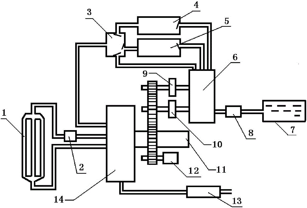
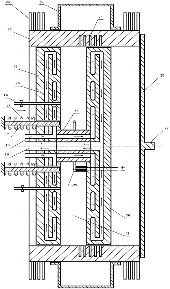
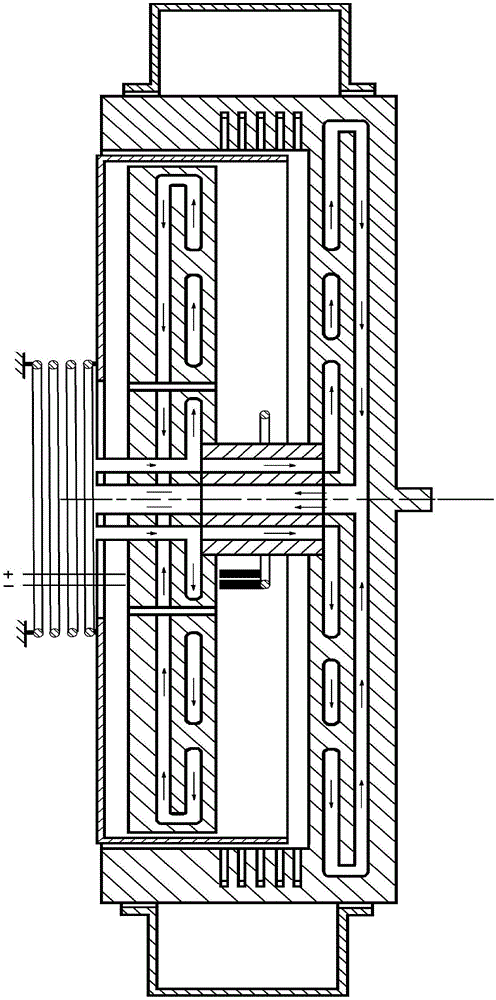
[0023] in figure 1 , 2 In the structure shown in the present invention, a rotary jet internal combustion engine designed by the present invention includes an electronic control unit (ECU), a rotary jet combustion chamber assembly 14, an air compression system, an emergency starter motor, an air storage device, a cooling system, and fuel Supply system, lubrication system, power generation storage equipment, exhaust gas processing device; electronic control unit (ECU) is similar in structure and function to the electronic control unit of ordinary internal combustion engines. It is the control center of the entire internal combustion engine. It uses sensors to collect accelerator, brake, temperature, pressure, Speed ​​and other parameters are analyzed and calculated, and then various switches, valves and other components...


PUM


Abstract

The invention relates to a rotating jet internal combustion engine. The rotating jet internal combustion engine comprises an electric control unit, a rotating jet combustion chamber assembly, an air compression system, an air storage device, a cooling system, a fuel supply system, a lubricating system, power generation storage equipment, an emergency starting motor and a tail gas treatment device. The fuel supply system is connected with the air compression system; the air compression system is connected with the air storage device; the air storage device is connected with the rotating jet combustion chamber assembly; the rotating jet combustion chamber assembly is connected with a power output shaft; the power output shaft is connected with the air compression system; the rotating jet combustion chamber assembly is further connected with the cooling system and the tail gas treatment device. According to the rotating jet internal combustion engine, the air storage tank is combined with the rotating jet combustion chamber assembly, a fuel and air mixture is combusted in the rotating jet combustion chamber assembly to output power, and the internal combustion engine can stably run under various working conditions; the problems that an existing internal combustion engine is low in heat efficiency, narrow in working rotating speed range and the like are solved; the internal combustion engine has the advantages of being wide in working rotating speed range, high in compression ratio, high in combustion efficiency and the like.

Description

Technical field [0001] The invention belongs to the technical field of power equipment, and relates to an internal combustion engine, in particular a rotary jet internal combustion engine. Background technique [0002] The internal combustion engine is a device that burns fuel inside the machine and directly converts the heat energy it emits into power. It is a heat engine that converts internal energy into mechanical energy. It is currently a power device widely used in the world. Small size, small quality, easy to move, high thermal efficiency, and good starting performance. [0003] The main principles of existing internal combustion engines are similar. Piston type internal combustion engines are the most common. They mix liquid or gaseous fuel with air and directly input it into the high-pressure combustion chamber inside the cylinder for combustion, and use the generated gas power to push the piston to move to generate power. In order to improve the thermal efficiency of int...

Claims


Application Information

Patent Timeline
Patent Type & Authority Patents(China)
IPC IPC(8): F02C3/14
Inventor 向兵
Owner 向兵
Learn More