Electrically operated valve device combining hand-operated inner lifting stop valve with double-shaft motor

A technology of electric valve device and double-axis motor, which is applied in the direction of valve device, valve operation/release device, engine components, etc., can solve the problems of high maintenance cost, high cost, low efficiency, etc., and achieve simple structure, low cost, cost reduction effect

Inactive Publication Date: 2015-01-07
赵继鹏
View PDF8 Cites 0 Cited by
  • Summary
  • Abstract
  • Description
  • Claims
  • Application Information

AI Technical Summary

Problems solved by technology

[0003] 1. The area of ​​the irrigated land is too large and too wide. The use of manual drip irrigation management is time-consuming and laborious, and the efficiency is very low. If the management is not in place, the irrigation time cannot be managed according to the specified time, especially at night, hot weather, and other unforeseen reasons. Mastering the irrigation time cannot meet the needs of scientific irrigation;
[0004] 2. It is impossible to further improve the modern management level of the existing water-saving irrigation agriculture;
[0005] 3. It is impossible to quickly and conveniently obtain the emergencies of on-site equipment and irrigation;
[0006] 4. Due to the lack of water resources and other issues, manual irrigation management is used, and water-saving measures cannot be implemented accurately and efficiently
Disadvantages: There is a control intermediat

Method used


Image

  • Electrically operated valve device combining hand-operated inner lifting stop valve with double-shaft motor
  • Electrically operated valve device combining hand-operated inner lifting stop valve with double-shaft motor
  • Electrically operated valve device combining hand-operated inner lifting stop valve with double-shaft motor

Examples


Embodiment Construction

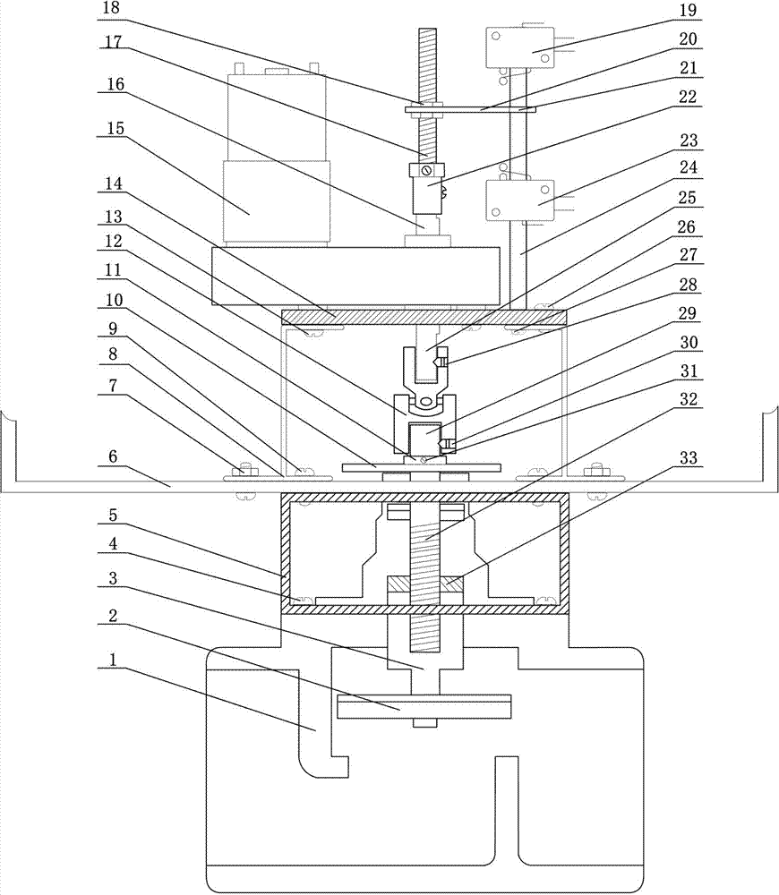
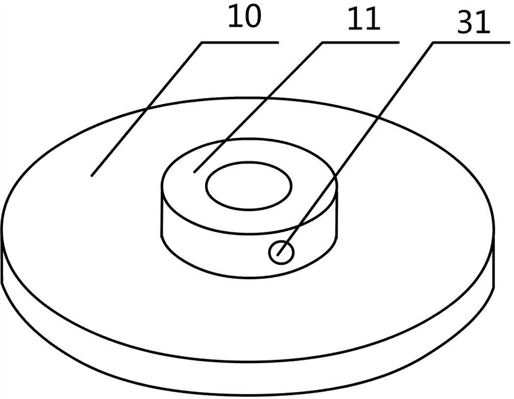
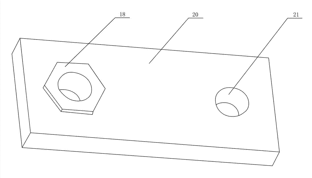
[0020] A manual internal lifting cut-off valve according to the present invention is equipped with a double-axis motor electric valve device. The electric valve controlled by the valve Bracket fixing bolts, inner bracket, inner and outer bracket fixing bolts, hand wheel, hand wheel fixing seat, universal joint, motor fixing screw, motor fixing plate, miniature geared motor, motor upper shaft, measuring position rotating rod, upper and lower position transmission plate bolts , Open valve travel switch, upper and lower position transmission plate, vertical rod hole of upper and lower position transmission plate, motor upper shaft coupling, valve closing travel switch, travel switch vertical rod, motor lower shaft, motor fixing plate fixing screw, vertical rod fixing screw , universal joint fastening motor shaft screw, valve drive shaft, universal joint fastening valve shaft screw, hand wheel fastening valve shaft screw, valve shaft thread, internal lifting body thread. Among the...


PUM


Abstract

The invention relates to an electrically operated valve device combining a hand-operated inner lifting stop valve with a double-shaft motor. The electrically operated valve device comprises a valve body, a valve cap, an inner lifting body, an outer frame fixing bolt, an outer frame, a box body, an inner bracket fixing bolt, an inner bracket, an inner and outer bracket fixing bolt, a hand wheel, a hand wheel fixing seat, a universal joint coupling, a motor fixing screw, a motor fixing plate, a micro-reducing motor, a motor upper shaft, a measuring position rotating bar, a upper and lower position transmission plate bolt, a valve opening travel switch, an upper and lower position transmission plate, an upper and lower position transmission plate upright hole, a motor upper shaft coupling, a valve closing travel switch, a travel switch upright, a motor lower shaft, a motor fixing plate fixing screw, a upright fixing screw, a universal joint coupling fastening motor shaft screw, a valve transmission shaft, a universal joint coupling fastening valve shaft screw, a hand wheel fastening valve shaft screw, a valve shaft thread and an inner lifting body thread. The device has the advantages that the operation is simple and convenient, the reliability is high, the power consumption and cost are low and the maintenance and management are facilitated; the device is suitable for the automatic control of large-scale drip irrigation and independent control.

Description

technical field [0001] The invention relates to an electric valve device equipped with a double-axis motor for a manual internal lift cut-off valve. Background technique [0002] Due to the scarcity of water resources and the prominent contradiction between water and soil, the promotion of water-saving irrigation technology has become a top priority. At present, the following phenomena exist in the use of artificial drip irrigation: [0003] 1. The area of ​​the irrigated land is too large and too wide. The use of manual drip irrigation management is time-consuming and laborious, and the efficiency is very low. If the management is not in place, the irrigation time cannot be managed according to the specified time, especially at night, hot weather, and other unforeseen reasons. Mastering the irrigation time cannot meet the needs of scientific irrigation; [0004] 2. It is impossible to further improve the modern management level of the existing water-saving irrigation agri...

Claims


Application Information

Patent Timeline
IPC IPC(8): F16K31/05
CPCF16K31/05
Inventor 赵继鹏王安江李青山王莉张丽周涛赵伽文白玮琦
Owner 赵继鹏
Why Eureka
Try Eureka