Initiative imaging method and system based on compressed sampling
An imaging system, compressed sampling technology, applied in the radio wave measurement system, electromagnetic wave re-radiation, utilization of re-radiation, etc., can solve the problems of slow speed, reduced imaging speed, inability to obtain high-speed images and videos, etc.
- Summary
- Abstract
- Description
- Claims
- Application Information
AI Technical Summary
Problems solved by technology
Method used
Image
Examples
Embodiment 1
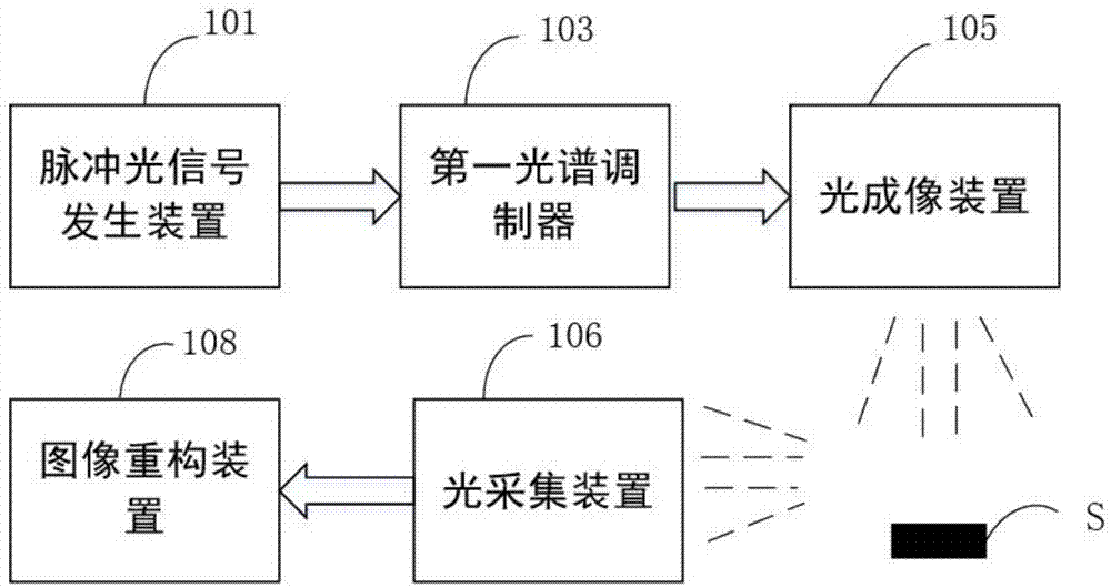
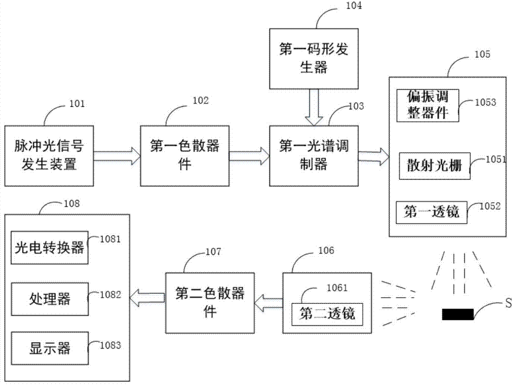
[0096] According to one embodiment of the present invention, the active imaging process is as follows.
[0097] Figure 1a with Figure 1b It is the imaging system architecture diagram of Embodiment 1, refer to Fig. 1, firstly, perform spectral modulation on the pulsed optical signal generated by the pulsed optical signal generating device, so that the optical signal is modulated with a compressed sampling measurement matrix sequence in the time domain.
[0098] In the embodiment of the present invention, a pulsed optical signal generator is used as the light source of the imaging system, and different pulsed signal generators generate optical signals with different spectral widths B. The pulsed light signal generating device 101 generates a pulsed light signal in a working state, and the pulsed light signal can be expressed as f(ω) in the frequency domain, where ω is the angular frequency of light. The pulsed optical signal f(ω) output by the pulsed optical signal generating...
Embodiment 2
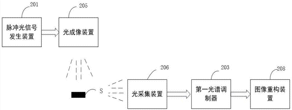
[0149] According to yet another embodiment of the present invention, the active imaging process based on compressed sampling is as follows.
[0150] Figure 2a with Figure 2b It is the structure diagram of the imaging system of the second embodiment, referring to Fig. 2, firstly, the pulse light signal is input to the optical imaging device for imaging processing;
[0151] In the embodiment of the present invention, a pulsed light signal generator is used as the light source of the imaging system, and different pulsed signal generators generate light signals with different spectral widths B. The pulsed light signal generating device 201 generates a pulsed light signal in a working state, and the pulsed light signal can be expressed as f(ω) in the frequency domain, where ω is the angular frequency of light. The pulsed optical signal f(ω) is input into the optical imaging system 205 for imaging. The optical imaging system generally includes a scattering grating 2051 and a len...
Embodiment 3
[0178] According to yet another embodiment of the present invention, the active imaging process based on compressed sampling is as follows.
[0179] Figure 3a with Figure 3b It is the imaging system architecture diagram of the third embodiment, referring to Fig. 3, the optical signal generator in the present embodiment adopts a pulseless light source, for example, an incoherent light source, and the phase between each spectral line of the incoherent light source has nothing to do, so it can Effectively, the amplitude of the optical signal is modulated on the light source. Optionally, a broadband incoherent light source may be used, and the broadband incoherent light source includes a multi-wavelength laser, a multi-wavelength laser array, a broadband noise light source, and the like.
[0180] performing the first spectral modulation on the optical signal generated by the optical signal generator 301;
[0181] First, the optical signal generator 301 generates an optical si...
PUM
 Abstract
Description
Claims
Application Information
 - R&D
- Intellectual Property
- Life Sciences
- Materials
- Tech Scout
- Unparalleled Data Quality
- Higher Quality Content
- 60% Fewer Hallucinations
Browse by: Latest US Patents, China's latest patents, Technical Efficacy Thesaurus, Application Domain, Technology Topic, Popular Technical Reports.
© 2025 PatSnap. All rights reserved.Legal|Privacy policy|Modern Slavery Act Transparency Statement|Sitemap|About US| Contact US: help@patsnap.com


