Layout method of multiple-input multiple-output imaging antenna in close range planar array

A technology of planar array and layout method, which is applied to antennas, antenna arrays, and structural forms of radiating elements, and can solve the problems of short-distance microwave imaging that cannot balance efficiency and imaging quality

Active Publication Date: 2016-07-13
INNER MONGOLIA UNIV OF TECH
View PDF6 Cites 2 Cited by
  • Summary
  • Abstract
  • Description
  • Claims
  • Application Information

AI Technical Summary

Problems solved by technology

[0013] The problem to be solved by the present invention is that short-distance microwave imaging cannot take into account both efficiency and imaging quality, and a layout method for short-distance planar array multi-input multi-output imaging antennas is provided

Method used


Image

  • Layout method of multiple-input multiple-output imaging antenna in close range planar array
  • Layout method of multiple-input multiple-output imaging antenna in close range planar array
  • Layout method of multiple-input multiple-output imaging antenna in close range planar array

Examples


Embodiment Construction

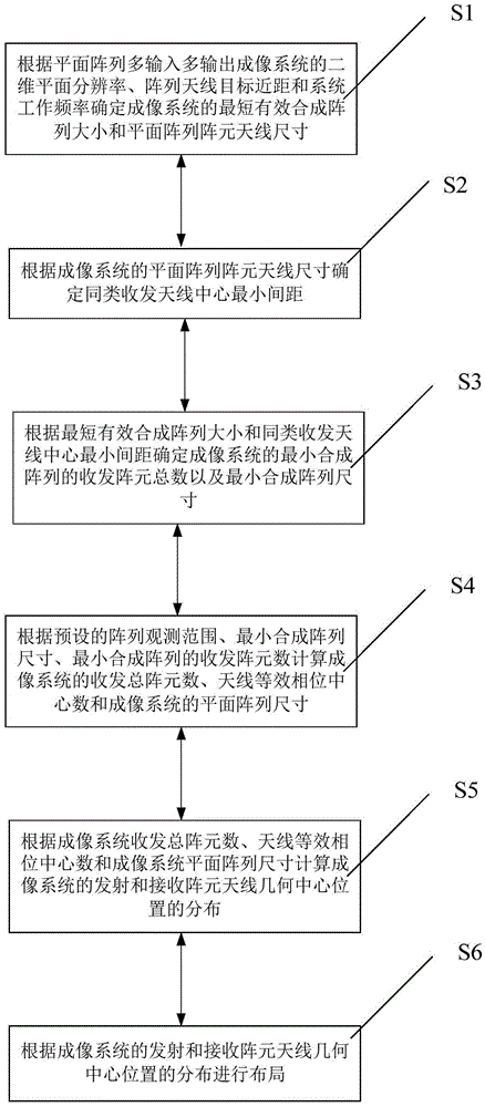
[0093]The present invention will be described in detail below in conjunction with the accompanying drawings. The steps involved in the text do not limit the steps of the layout method of the present invention unless there is a contextual logical connection.

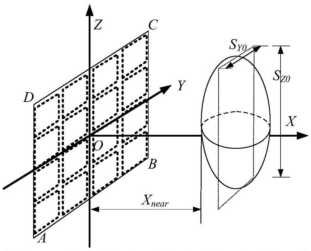
[0094] Such as figure 1 As shown, it is a layout method of a short-distance planar array MIMO imaging antenna provided by the present invention, wherein, the two-dimensional plane of the planar array MIMO imaging system includes the pitch direction (that is, the Z-axis direction) and the azimuth direction (that is, the Y-axis direction) axis direction), X near is the short distance of the array antenna target, that is, the shortest distance between the observation target and the plane array antenna face (denoted as ABCD), the origin O(0,0) is the geometric center of the MIMO imaging system plane array, S Y0 and S Z0 Respectively represent the target observation range along the Y-axis and Z-axis directions. Same as the...


PUM


Abstract

The invention discloses a layout method of a short-distance planar array MIMO imaging antenna, comprising: step S1: determining the shortest effective synthetic array size and the size of the planar array element antenna of the imaging system; step S2: determining the minimum distance between the centers of the receiving and transmitting antennas of the same type; step S3: Determine the total number of transceiver elements and the size of the minimum composite array of the imaging system; Step S4: Calculate the total number of transceiver elements of the imaging system, the number of antenna equivalent phase centers, and the planar array size of the imaging system; Step S5: Calculating the distribution of the geometric center positions of the transmitting and receiving array element antennas of the imaging system; Step S6: performing layout according to the distribution of the geometric center positions of the transmitting and receiving array element antennas of the imaging system. The layout method of the present invention solves the problem that the effective synthesis array length is affected by the observation distance in planar array MIMO imaging, and further improves the data acquisition efficiency on the premise of ensuring the quality of short-distance microwave images.

Description

technical field [0001] The invention relates to the field of short-distance microwave imaging observation, in particular to a short-distance planar array multi-input multi-output imaging antenna layout method. Background technique [0002] Short-range microwave imaging technology is not affected by lighting and other conditions, and has the advantages of being able to penetrate certain obstacles. It is playing an increasingly important role in the fields of safety inspection, non-destructive inspection, and radar target imaging diagnosis. According to the actual application characteristics, the observation range of short-distance microwave imaging is usually within 2m or within 10m. The conventional method of using a single antenna to move along a two-dimensional plane to obtain the echo data of the observed target takes a long time and is inefficient, which is only suitable for experimental verification. , but not suitable for practical system applications. [0003] David ...

Claims


Application Information

Patent Timeline
Patent Type & Authority Patents(China)
IPC IPC(8): H01Q1/36H01Q21/00
Inventor 黄平平谭维贤洪文王彦平
Owner INNER MONGOLIA UNIV OF TECH
Why Eureka
Try Eureka