
Method for detecting sulphur poisoning in an exhaust treatment system

A technology for exhaust gas post-treatment and exhaust gas flow, which is applied in the electronic control of exhaust gas treatment devices, diagnostic devices of exhaust gas treatment devices, and exhaust gas treatment, etc. It can solve the problem of no indication of sulfur poisoning.

Inactive Publication Date: 2015-01-07
SCANIA CV AB
View PDF9 Cites 24 Cited by
  • Summary
  • Abstract
  • Description
  • Claims
  • Application Information

AI Technical Summary

Problems solved by technology

There is currently no reliable method for obtaining an indication of sulfur poisoning, and the purpose of the present invention is to give such a method

Method used


Image

  • Method for detecting sulphur poisoning in an exhaust treatment system
  • Method for detecting sulphur poisoning in an exhaust treatment system
  • Method for detecting sulphur poisoning in an exhaust treatment system

Examples


Embodiment Construction

[0033] Preferred embodiments of the present invention will now be described with reference to the accompanying drawings.

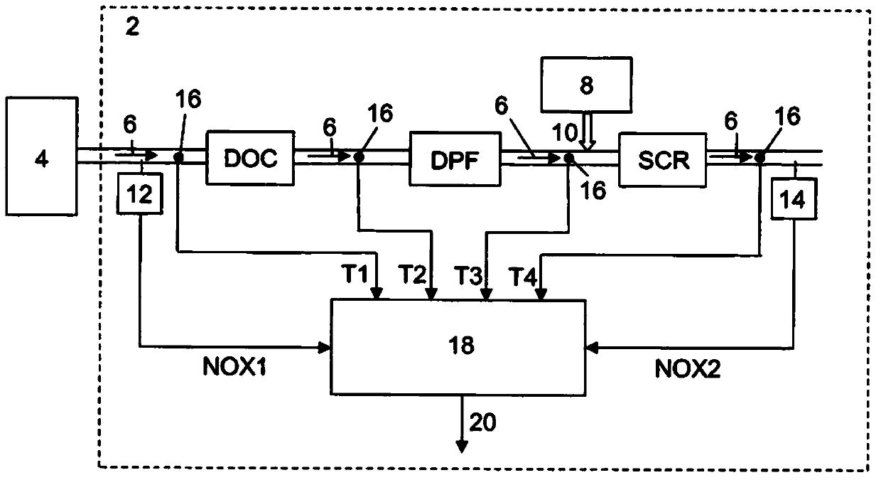
[0034] figure 1 is a schematic diagram of the exhaust gas aftertreatment system according to the present invention.

[0035] figure 1 An exhaust gas aftertreatment system 2 for a combustion engine 4 which generates an exhaust gas flow 6 is depicted. System 2 includes a system designed to convert NO into NO 2 at least one diesel oxidation catalyst (DOC) and at least one selective catalytic reduction catalyst (SCR catalyst). A Diesel Particulate Filter (DPF) is also preferably located downstream of the DOC. This filter can be uncoated or provided with a catalytic coating. Here soot and ash are collected and NO to NO 2 A certain degree of transformation also takes place here.

[0036] The system also comprises a reductant device 8 adapted to supply a reductant 10 such as urea or ammonia to the exhaust gas flow 6 upstream of the SCR catalyst, NO and NO ...


PUM


Abstract

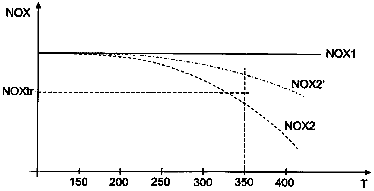
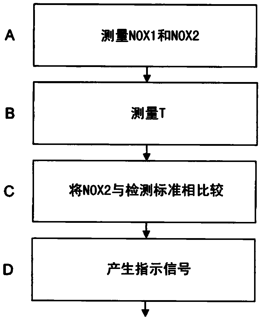
The invention relates to an exhaust post-treatment system (2) for a combustion engine (4) which produces an exhaust flow (6), which system (2) comprises at least one diesel oxidation catalyst (DOC) and / or at least one diesel particle filter (DPF), and at least one selective reduction catalyst (SCR catalyst). The system further comprises a reducing agent device (8) adapted to supplying a reducing agent (10) to the exhaust flow (6) upstream of said SCR catalyst, a first NOx sensor (12) situated upstream of said DOC and / or DPF and adapted to measuring the content of nitrogen oxide compounds (NOx) in the exhaust flow and to producing on the basis thereof a first NOx output signal (NOX1), a second NOx sensor (14) situated downstream of said SCR catalyst and adapted to measuring the content of nitrogen oxide compounds (NOx) in the exhaust flow and to producing on the basis thereof a second NOx output signal (NOX2), and at least one temperature sensor (16) adapted to monitoring the temperature of the exhaust flow and to producing on the basis thereof at least a first temperature signal (T1). The exhaust post- treatment system (2) comprises a calculation unit (18) to which said first and second NOx output signals (NOXl, NOX2) and said first temperature signal (T1) are arranged to be conveyed, said first and second NOx sensors (12, 14) are adapted to measuring the content of nitrogen oxide compounds NOX1 upstream of said DOC and / or DPF and to measuring at substantially the same time the content of nitrogen oxide compounds NOX2 downstream of the SCR catalyst when no reducing agent (10) is being supplied to the exhaust flow (6) from the reducing agent device (8), and said temperature sensor (16) is adapted to measuring the temperature T when the measurements of NOXl and NOX2 are taking place, which calculation unit (18) is adapted to comparing NOX2 with a detection criterion, which preferably comprises comparing with a predetermined threshold value NOXtr related to the measured temperature, and to generating on the basis of the comparison an indicating signal (20).

Description

technical field [0001] The invention relates to an exhaust gas aftertreatment system and a method related to said system according to the preambles of the independent claims. [0002] In particular, the method and the system are suitable for detecting sulfur poisoning of a Diesel Oxidation Catalyst (DOC) in an exhaust gas aftertreatment system. Background technique [0003] Combustion engines burn a mixture of air and fuel to generate propulsion. The combustion process produces exhaust gases that are passed from the engine to the atmosphere. Exhaust gases include nitrogen oxides (NO x ), carbon dioxide (CO 2 ), carbon monoxide (CO), and particulate matter. NO x Is a synthetic term used to refer to nitrogen monoxide (NO) and nitrogen dioxide (NO 2 ) constitutes exhaust gas. Exhaust aftertreatment systems treat exhaust emissions to reduce them before they are released into the atmosphere. In an exemplary exhaust aftertreatment system, a dosing system injects a reductan...

Claims


Application Information

Patent Timeline
IPC IPC(8): F01N3/20F01N3/08F01N9/00F01N11/00
CPCF01N2900/1606F01N2560/14F01N11/002Y02T10/47F01N2900/1621F01N2550/02F01N2900/1602F01N3/103F01N2570/04F01N2560/06F01N13/009F01N3/2066F01N2900/0412F01N2900/1402F01N2550/04F01N2560/026F01N2900/0416F01N3/106Y02T10/40F01N3/0885F01N9/00F01N11/00F01N2900/1404
Inventor O·斯滕洛斯
Owner SCANIA CV AB
Learn More