
Protection device for carrying out girth welding on nuclear class equipment cylinder and girth welding technology

A protective device and girth welding technology, applied in the direction of providing/removing protective gas devices, welding equipment, welding accessories, etc., can solve the problems of high cost, difficult operation, limited use, etc., and achieve good quality and fast welding speed Effect

Active Publication Date: 2015-01-14
CHINA NUCLEAR POWER ENG CO LTD
View PDF9 Cites 12 Cited by
  • Summary
  • Abstract
  • Description
  • Claims
  • Application Information

AI Technical Summary

Problems solved by technology

[0002] At present, in the field of nuclear power, most of the equipment cylinder or pipe girth welds are designed with full penetration, and the welding process generally adopts double-sided welding, that is, after the front weld bead is completed, the back weld bead is cleaned, and then the back weld bead is welded. This method is efficient Low, difficult to operate when welding on the back, and only suitable for welding large-diameter pipes
Another method is to use annular ceramic liners for single-sided welding and double-sided molding in order to improve efficiency, and make special-sized annular ceramic liners for welding according to the size of the pipe or equipment cylinder. The disadvantage of this method is that the ceramic liners are one-time permanent welding accessories, high cost, cumbersome production and assembly process, which limits the use of this method
At present, there is another argon-electricity combined welding process used for the welding of pipeline girth welds, that is, argon arc welding is used to make the bottom, and manual arc welding is used to cover the surface. Although the efficiency has been improved, there are still big problems in the protection of the back weld bead.

Method used


Image

  • Protection device for carrying out girth welding on nuclear class equipment cylinder and girth welding technology
  • Protection device for carrying out girth welding on nuclear class equipment cylinder and girth welding technology
  • Protection device for carrying out girth welding on nuclear class equipment cylinder and girth welding technology

Examples


Embodiment Construction

[0034] The present invention will be described in detail below in conjunction with the accompanying drawings and embodiments.

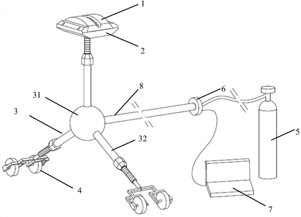
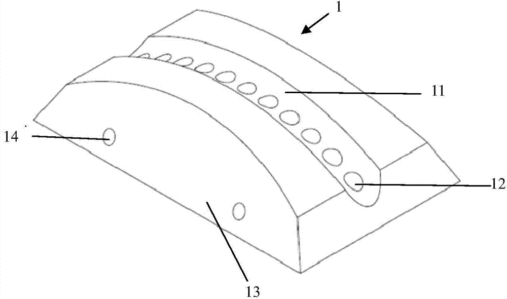
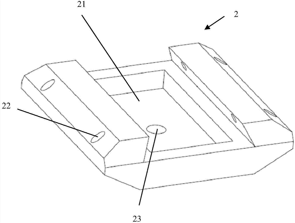
[0035] Such as figure 1 As shown, the nuclear-level equipment cylinder circular seam welding protection device of the present invention consists of a detachable lining block 1, a supporting block 2, an adjustable outrigger mechanism 3, a protective gas supply device 5, a traveling mechanism 4, a speed regulator 6 and The control computer consists of 7 components. The detachable lining block 1 is arranged on the support block 2, and the adjustable outrigger mechanism 3 is provided under the support block 2, and the adjustable outrigger mechanism 3 is connected to the protective gas supply device 5 through the insertion rod (8); Both the adjustable outrigger mechanism 3 and the insertion rod 8 are provided with a protective gas channel, and the protective gas channel communicates with the protective gas supply device 5 and the gas collection groove 21 ...


PUM


Abstract

The invention relates to a girth welding technology of a nuclear class equipment cylinder, in particular to a protection device for carrying out girth welding on the nuclear class equipment cylinder and a girth welding technology. The protection device comprises a detachable lining block, wherein the detachable lining block is adapted to the inner surface of a to-be-welded equipment cylinder, and multiple shielding gas through holes which are arranged along the welding seam direction are formed in the detachable lining block; the detachable lining block is arranged on a supporting block, an adjustable supporting leg mechanism is arranged under the supporting block, and the adjustable supporting leg mechanism is connected with a shielding gas supplying device through an inserting rod; shielding gas passages are formed in the adjustable supporting leg mechanism and the inserting rod, and the shielding gas passages are communicated with the shielding gas supplying device and a gas collection groove of the supporting block; the adjustable supporting leg mechanism is connected with a walking mechanism, and an electric motor of the walking mechanism is connected with a control device. The protection device disclosed by the invention rotates annually according to the welding speed, the welding efficiency is increased, the characteristics of automation and multi-adaptability are obtained while welding seam back forming and gas protection are ensured, the welding effect is good, and the utilization rate is high.

Description

technical field [0001] The invention relates to a nuclear-grade equipment cylinder welding process, in particular to a protective device and a circular seam welding process that can be used for nuclear-grade equipment cylinder circular seam welding. Background technique [0002] At present, in the field of nuclear power, most of the equipment cylinder or pipe girth welds are designed with full penetration, and the welding process generally adopts double-sided welding, that is, after the front weld bead is completed, the back weld bead is cleaned, and then the back weld bead is welded. This method is efficient Low, it is not easy to operate when welding on the back, and it is only suitable for welding large-diameter pipes. Another method is to use annular ceramic liners for single-sided welding and double-sided molding in order to improve efficiency, and make special-sized annular ceramic liners for welding according to the size of the pipe or equipment cylinder. The disadvan...

Claims


Application Information

Patent Timeline
IPC IPC(8): B23K9/16B23K9/32
CPCB23K9/0282B23K9/035B23K9/16B23K9/32B23K9/325
Inventor 王宇欣郭利峰沈艳祥邵联利于坚董安胡忠全王勇王恒石立波邓峰
Owner CHINA NUCLEAR POWER ENG CO LTD
Features
  • Generate Ideas
  • Intellectual Property
  • Life Sciences
  • Materials
  • Tech Scout
  • Unparalleled Data Quality
  • Higher Quality Content
  • 60% Fewer Hallucinations
Learn More