
Novel anti-rotation rolling wheel ascending and descending tappet

A roller lifting and anti-rotation technology, applied in engine components, machines/engines, mechanical equipment, etc., can solve the problems of high production costs, wear of anti-rotation devices, complex processing procedures, etc. simple structure

Active Publication Date: 2015-01-14
武汉东方骏驰精密制造有限公司
View PDF9 Cites 5 Cited by
  • Summary
  • Abstract
  • Description
  • Claims
  • Application Information

AI Technical Summary

Problems solved by technology

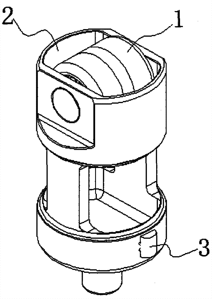
[0005] Although the above two methods solve the problem of the relative position change between the roller lift tappet and the cam, the first fixing method, because the roller lift tappet is doing reciprocating linear motion, the anti-rotation device is in contact with the cylinder head for a long time. Or the guide part of the pump housing interacts, it is easy to fall off and affect its use; the second fixing method needs to process grooves on the main body of the roller lifting tappet, and the structure of the anti-rotation device is complicated, which leads to complicated processing procedures , The production cost is high, and the anti-rotation device is always in frictional contact with the outside world during the reciprocating linear motion of the tappet, which will easily cause the anti-rotation device to wear and cause the anti-rotation effect of the anti-rotation device to deteriorate, and it is difficult to meet the actual need

Method used


Image

  • Novel anti-rotation rolling wheel ascending and descending tappet
  • Novel anti-rotation rolling wheel ascending and descending tappet
  • Novel anti-rotation rolling wheel ascending and descending tappet

Examples


Embodiment approach

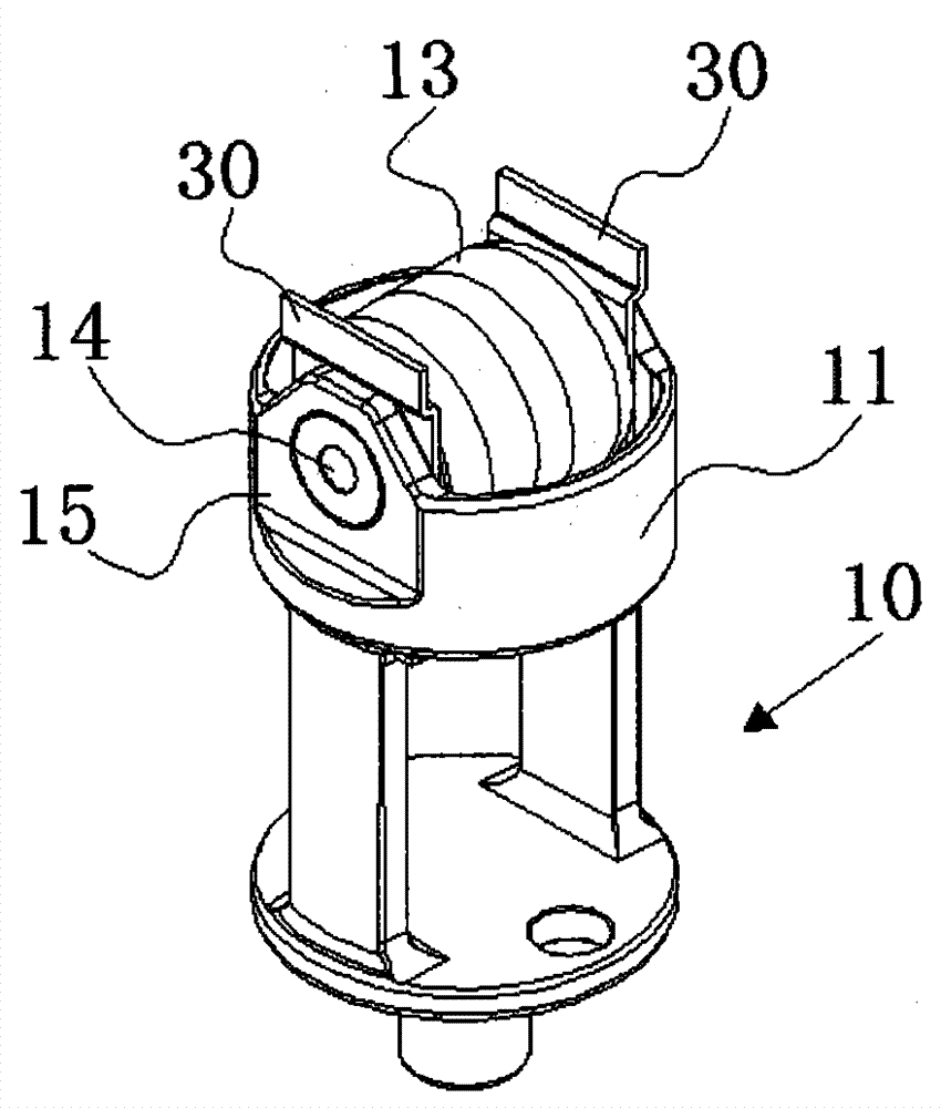
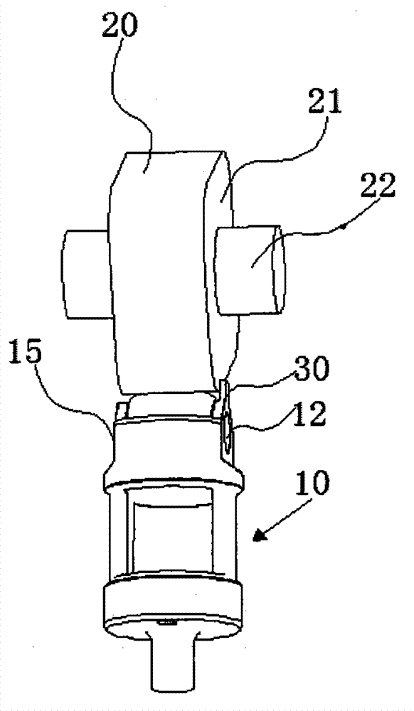
[0029] Please keep reading image 3 As shown, as the second embodiment of the present invention, the anti-rotation card 30 of the present invention can also be an ear plate provided on the platform 15 of the housing 11, and the ear plate is formed by the housing 11 on the side of the cam 20. The end faces the end plate extending in the direction of the cam 20, and the distance between the highest point of the lug plate near the side of the cam 20 and the center line of the pin hole 14 is greater than the radius of the roller 13, wherein the lug plate can be integrally formed with the platform, It can also be formed by welding a flat plate on the platform of the shell 11. That is, during the movement, since the relative position of the cam 20 does not change, and once the tappet 10 rotates reversely, causing the relative position of the roller 13 and the cam 20 to change, the end face of the cam 20 will exert a force on the lug plate beyond the roller. On the end face on the 13 ...


PUM


Abstract

The invention provides a novel anti-rotation rolling wheel ascending and descending tappet, which comprises a tappet rod and a cam periodically acting on the tappet rod, wherein the tappet rod comprises a casing, a pin shaft and a rolling wheel arranged on the pin shaft, the casing is in a hollow cylinder shape, two coaxial pin holes are formed in the casing, the pin shaft is used for installing the rolling wheel on the casing through the pin holes, two mutually symmetrical platforms which are formed through milling are arranged on the outer circle surface arranged at one side, near the cam, of the casing, the platforms extend to the end surface of the casing, the pin holes are formed in the platforms, an anti-rotation clamp plate is arranged on the end surface part of the rolling wheel, in addition, the space between the top surface, near the cam, of the anti-rotation clamp plate and a center line of the pin shaft is greater than the outer diameter of the rolling wheel, and the anti-rotation clamp plate approaches to the cam but is not in contact with the cam. The invention provides the novel anti-rotation rolling wheel ascending and descending tappet with the advantages of simple structure, good anti-rotation effect and low processing cost.

Description

Technical field [0001] The invention relates to an engine valve lifter, in particular to a novel anti-rotation roller lifting lifter. Background technique [0002] A tappet is a device that converts the rotary motion of a rotating mechanism such as a cam into linear motion. In the valve mechanism of an internal combustion engine, when the tappet is set directly below the camshaft, when the cam on the camshaft moves further, it contacts the associated ventilation valve through the push rod and rocker arm. In most cases, it is designed as a cup-shaped tappet, and the tappet is directly placed between the cam and the ventilation valve. In pump transmissions, the tappet is also usually arranged directly between the cam of the pump drive shaft and the corresponding pump piston. [0003] In addition, in order to minimize friction, a curved rolling surface is usually formed on the outer body of the tappet or the outer body is provided with rolling rollers. The rolling rollers are rotata...

Claims


Application Information

Patent Timeline
IPC IPC(8): F01L1/14F01L1/16
CPCF01L1/143F01L2303/00F01L2305/00F01L2307/00
Inventor 朱塞佩·Z汉斯·L
Owner 武汉东方骏驰精密制造有限公司
Learn More