Surface enhanced Raman spectroscopy (SERS) sensing substrate and manufacturing method thereof

A surface-enhanced Raman and substrate technology, applied in Raman scattering, material excitation analysis, etc., can solve problems such as expensive and limited development

Inactive Publication Date: 2015-01-14
任贻均 +1
View PDF5 Cites 9 Cited by
  • Summary
  • Abstract
  • Description
  • Claims
  • Application Information

AI Technical Summary

Problems solved by technology

[0003] After the invention of laser in 1960, laser began to be used in Raman spectroscopy as an excitation source in 1964 to ampli

Method used


Image

  • Surface enhanced Raman spectroscopy (SERS) sensing substrate and manufacturing method thereof
  • Surface enhanced Raman spectroscopy (SERS) sensing substrate and manufacturing method thereof
  • Surface enhanced Raman spectroscopy (SERS) sensing substrate and manufacturing method thereof

Examples


Embodiment Construction

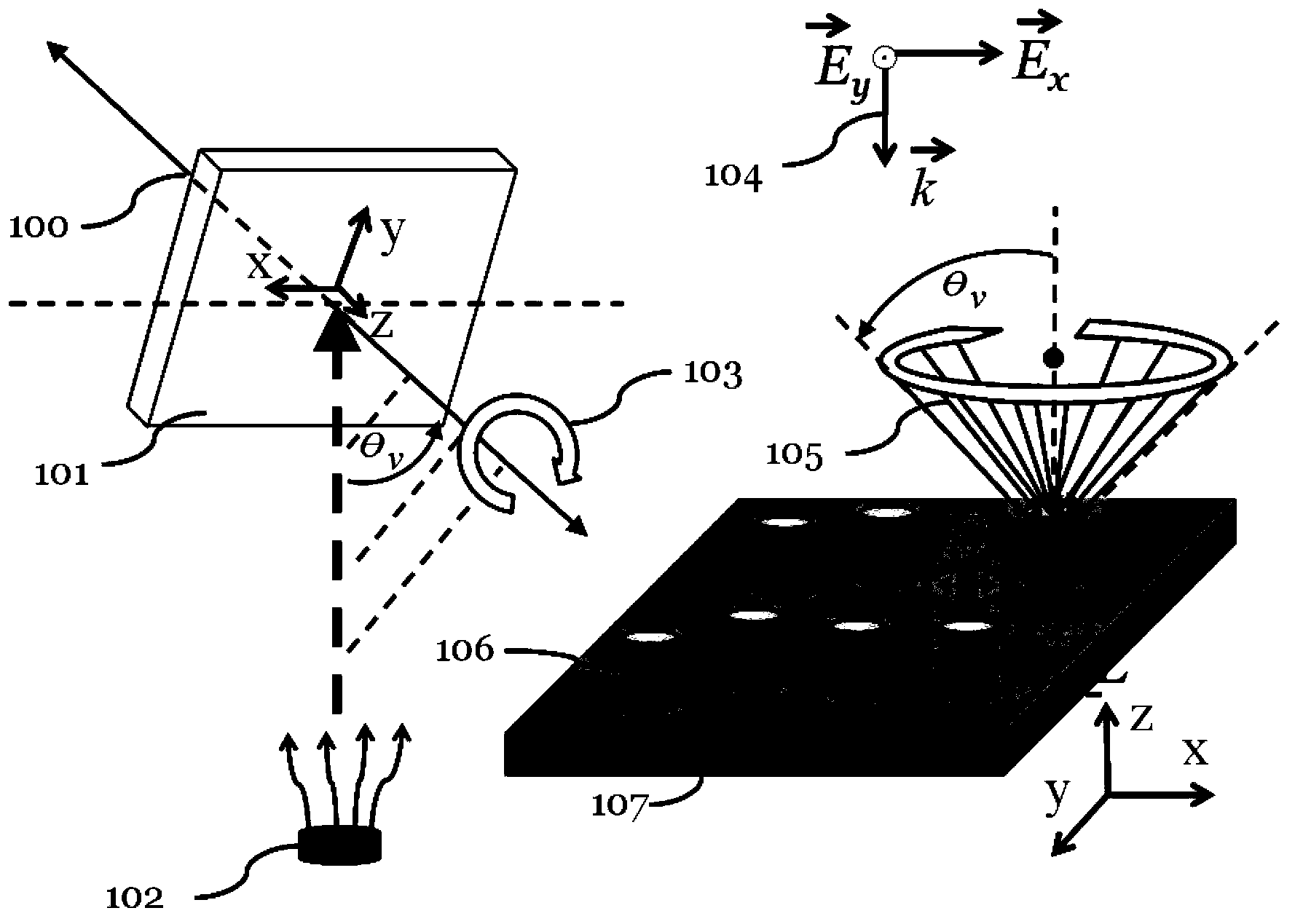
[0044] In order to solve the above technical problems, the present invention provides a method for manufacturing a surface-enhanced Raman spectroscopy (SERS) substrate with at least a metal nano-column structure, including: using an oblique angle deposition method with the rotation of the substrate, and fabricating on the substrate The metal nano column structure and / or the dielectric nano column structure, the nano column structure has a configuration, and the nano column structure is approximately parallel to the normal direction of the substrate after the growth is completed.

[0045] In the electron gun cavity system, such as figure 1 As shown, the present invention uses oblique angle deposition (oblique angle deposition) with substrate (self) rotation technology to fabricate a silicon wafer substrate 101 (or 107) or a glass substrate 101 (or 107) A plurality of silver nanopillar structures 106, the diameter of the structure is D, and the height (or thickness) is L.

[0046] Th...


PUM

PropertyMeasurementUnit
Diameteraaaaaaaaaa

Abstract

The invention relates to a surface enhanced Raman spectroscopy (SERS) sensing base plate. A first embodiment of the invention comprises a base plate and a nanometer straight column structure formed by a plurality of layers of metal/dielectric substance materials growing on the base plate, wherein the nanometer straight column structure is provided with a configuration and is roughly parallel to the normal direction of the base plate after growing up.

Description

Technical field [0001] The present invention is related to a surface enhanced Raman spectroscopy (SERS) sensing substrate and its manufacturing method, in order to solve the technical problem of enhancing the Raman signal of the object under test. Background technique [0002] Raman discovered the Raman scattering method in 1928, which belongs to the use of light scattering behavior to measure the vibrational spectral signal (Raman spectrum) of molecules. However, due to the very small cross-section of the molecular beam, it is difficult to measure the Raman signal, and it is gradually replaced by infrared light absorption spectrum. [0003] After the laser was invented in 1960, the laser began to be used in Raman spectroscopy as an excitation source in 1964 to enable signal amplification, but Raman spectrometers are still much more expensive than infrared spectrometers, which limits their development. In 1974, M. Fleischmann et al. found that rough metal surfaces can greatly incr...

Claims


Application Information

Patent Timeline
IPC IPC(8): G01N21/65
Inventor 任贻均游竟维
Owner 任贻均
Why Eureka
Try Eureka