Raman spectrometer for detecting specific narrow wave number range

A Raman spectrometer and range technology, applied in the field of Raman spectrometer, can solve problems such as low signal-to-noise ratio, destruction of biological samples, weak inherent features, etc., and achieve the effect of improving signal-to-noise ratio, avoiding interference, and intuitive results

Pending Publication Date: 2017-12-12
上海氘峰医疗科技有限公司
View PDF5 Cites 9 Cited by
  • Summary
  • Abstract
  • Description
  • Claims
  • Application Information

AI Technical Summary

Problems solved by technology

In this way, the emitted laser light is uniformly dispersed, and only one photon in every ten million photons undergoes Raman scattering, which makes the Raman signal itself weaker, resulting in a lower signal-to-noise ratio of the spectrum in the measurement range.
In order to obtain high-precision Raman spectra, higher laser intensity and longer acquisition time are required, which is likely to cause damage to samples, especially biological samples, and a higher time cost

Method used


Image

  • Raman spectrometer for detecting specific narrow wave number range
  • Raman spectrometer for detecting specific narrow wave number range
  • Raman spectrometer for detecting specific narrow wave number range

Examples


Embodiment 1

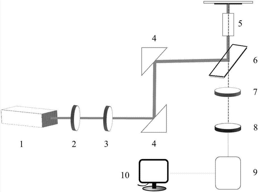
[0047] Raman spectrometers for detection of specific narrow wavenumber ranges such as figure 1 As shown, the spectrometer is mainly composed of laser emission equipment, spectrum acquisition equipment, and data processing equipment; the laser emission equipment includes a laser 1, an interference filter 2, and a power attenuation sheet 3; the spectrum acquisition equipment includes a microscope system 5, Rayleigh filter 6, confocal pinhole 7, bandpass filter 8, single photon detector 9; Described data processing equipment comprises computer equipment 10, and computer equipment 10 built-in processing software; Reflective mirror 4 realizes light path control.

[0048] The working process of the Raman spectrometer in this embodiment is as follows: the laser 1 emits laser light of a specific wavelength, filters out the plasma line through the interference filter 2, passes the light consistent with the expected wavelength of the emitted laser light, and controls the contact with th...

Embodiment 2

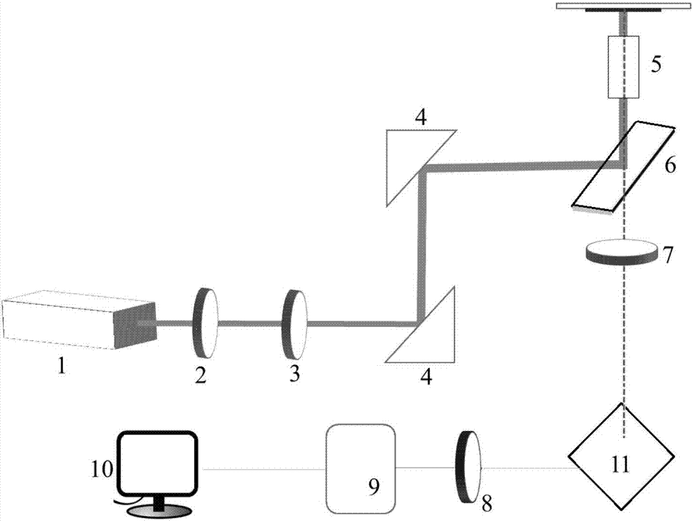
[0051] Raman spectrometers for detection of specific narrow wavenumber ranges such as figure 2 As shown, the spectrometer is mainly composed of laser emission equipment, spectrum acquisition equipment, and data processing equipment; the laser emission equipment includes a laser 1, an interference filter 2, and a power attenuation sheet 3; the spectrum acquisition equipment includes a microscope system 5, Rayleigh filter 6, confocal pinhole 7, grating 11, bandpass filter 8, single photon detector 9; Described data processing equipment comprises computer equipment 10, and computer equipment 10 built-in processing software; Reflector 4 is added to the turning part to realize optical path control.

[0052] The working process of the Raman spectrometer in this embodiment is as follows: the laser 1 emits laser light of a specific wavelength, filters out the plasma line through the interference filter 2, passes the light consistent with the expected wavelength of the emitted laser l...


PUM

PropertyMeasurementUnit
widthaaaaaaaaaa

Abstract

The invention relates to a raman spectrometer for detecting a specific narrow wave number range. The raman spectrometer comprises laser transmitting equipment, spectrum collection equipment and data processing equipment, wherein the laser transmitting equipment is used for obtaining a power regulated exciting light beam; the spectrum collection equipment is used for lighting the power regulated exciting light beam to the surface of a sample to perform raman scattering, filtering off oriented rayleigh scattered light to obtain oriented raman scattered light, and allowing the oriented raman scattered light to be received by a receiver; the data processing equipment is computer equipment connected with the receiver, and is used for formation, analysis and judgment of an obtained raman spectrum; the receiver is a single photon detector; and the oriented raman scattered light is finally received by the single photon detector. Compared with the prior art, the raman spectrometer can realize high-efficiency utilization of a photon, and can realize rapid and high-sensitivity detection of the raman spectrum of the specific narrow wave number range.

Description

technical field [0001] The invention relates to a Raman spectrometer, in particular to a Raman spectrometer for detecting a specific narrow wavenumber range. Background technique [0002] At present, the Raman spectrometers used in the market, including scientific research and portable, are generally aimed at a wider range of wavenumbers to obtain richer spectral information. In this way, the emitted laser light is uniformly dispersed, and only one photon in every ten million photons undergoes Raman scattering, which makes the Raman signal itself weaker, resulting in a lower signal-to-noise ratio of the spectrum in the measurement range. In order to obtain a high-precision Raman spectrum, a higher laser intensity and a longer acquisition time are required, which is likely to cause damage to samples, especially biological samples, and a higher time cost. [0003] Therefore, for Raman applications with selected marker peaks, narrowing the detection range to spectral signal co...

Claims


Application Information

Patent Timeline
Patent Type & Authority Applications(China)
IPC IPC(8): G01N21/65G01N21/01
CPCG01N21/01G01N21/658G01N2201/068G01N2021/0106
Inventor 王允
Owner 上海氘峰医疗科技有限公司
Why Eureka
Try Eureka