Circular saw blade supply and receiving device for automatic reaming device for central hole of circular saw blade
What is Al technical title?
Al technical title is built by PatSnap Al team. It summarizes the technical point description of the patent document.
A technology of circular saw blade and receiving device, which is applied in reaming device, hole reaming device, maintenance and safety accessories, etc., can solve the problems of easy injury of sharp edges, large area, and no technical enlightenment.
Inactive Publication Date: 2016-07-06
SUZHOU VOCATIONAL UNIV
View PDF9 Cites 6 Cited by
Summary
Abstract
Description
Claims
Application Information
AI Technical Summary
This helps you quickly interpret patents by identifying the three key elements:
Problems solved by technology
Method used
Benefits of technology
Problems solved by technology
Conveying the circular saw blades with a conveyor belt has the disadvantages of difficult control of the conveying section, poor running stability of the conveyor belt, and large space occupation of the workplace; the operator feeds the circular saw blades one by one to the feeding manipulator, which has a high work intensity for the operator. , waste of human resources, loss of safety, and the sharp edge of the sawtooth is easy to hurt the operator's fingers, etc.
In the prior art, the reamed circular saw blades are output by the same output conveyor belt, and the reamed circular saw blades are extracted from the drilling machine workbench by the receiving manipulator and released to the output conveyor belt. The output conveyor belt also has a large floor space and causes inconvenience to the packing and packaging of subsequent stations.
[0007] It can be seen from this that designing a circular saw blade supply and receiving device with a reasonable structure has positive significance for perfecting the structural system of the automatic reaming device for the central hole of the circular saw blade. For this reason, the applicant has done a literature search, but so far There are no technical inspirations that can be used for reference in the published patents and non-patent literature
Method used
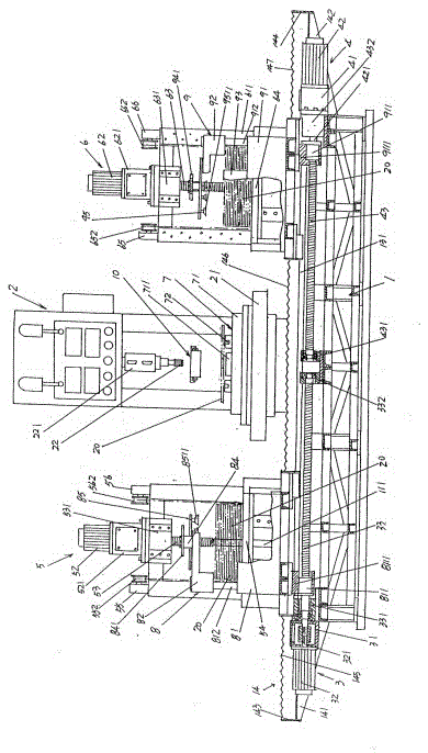
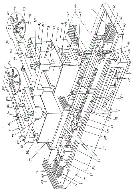
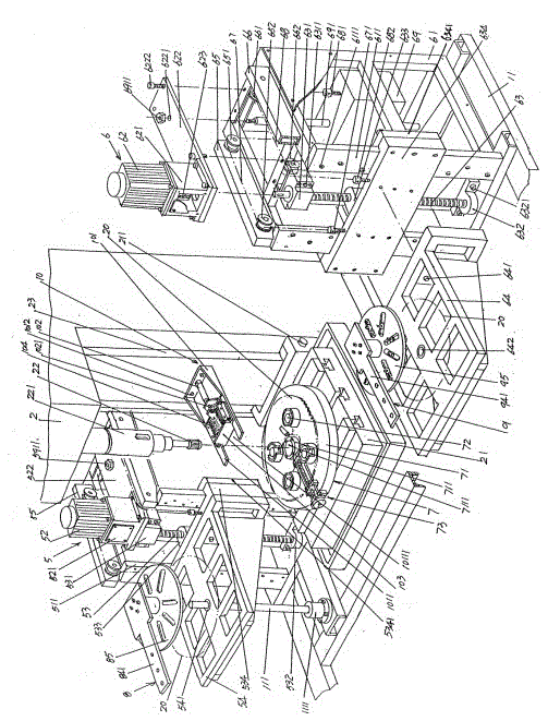
Image
Click on the blue label to locate the original text in one second.
Reading with bidirectional positioning of images and text.
Examples
Embodiment Construction
[0026] In order to enable the examiners of the patent office, especially the public, to understand the technical essence and beneficial effects of the present invention more clearly, the applicant will describe in detail the following in the form of examples, but none of the descriptions to the examples is an explanation of the solutions of the present invention. Any equivalent transformation made according to the concept of the present invention which is merely formal but not substantive shall be regarded as the scope of the technical solution of the present invention.
[0027] In the following descriptions, all concepts involving up, down, left, right, front and rear directionality (or orientation) are for the position state of the picture being described, and the purpose is to facilitate the public Therefore, it cannot be understood as a special limitation on the technical solution provided by the present invention.
[0028] See figure 1 , the structural system of the auto...
PUM
Abstract
The invention discloses a disk saw blade feeding and receiving device of and an automatic reaming device for a disk saw blade center hole, and belongs to the technical field of metal saw blade processing machinery. The automatic reaming device for the disk saw blade center hole comprises a base, a vertical drill, a receiving manipulator translating and driving mechanism, a feeding and receiving manipulator; the disk saw blade feeding and receiving device comprises a feeding and lifting gear and a receiving and lifting gear, the feeding and lifting gear comprises a feeding rack, a feeding motor, a feeding screw, a feeding and lifting gear, a left chain wheel seat of a feeding frame, a chain seat of the feeding mechanism, a first chain, a second chain and a balance block; the receiving and lifting gear comprises a receiving frame, a receiving motor, a receiving screw, a receiving and lifting platform, a left chain wheel seat of a receiving frame, a chain block of the receiving frame, a first lifting chain, a second lifting chain and a balance hammer. The disk saw blade feeding and receiving device is good in automation effect, working strength can be alleviated, safety can be ensured, the applicability to an operation place can be improved, human input can be reduced, and labor resource can be saved.
Description
technical field [0001] The invention belongs to the technical field of metal saw blade processing machinery, and in particular relates to a circular saw blade supply and receiving device for an automatic reaming device for a central hole of a circular saw blade. Background technique [0002] Since the material, structure, use and working principle of the circular saw blade mentioned above are well known in the industry, for example, please refer to the Chinese invention patent application publication number CN1311089A (circular saw blade), publication number CN102975236A (a circular saw blade structure), authorized announcement number CN202517132U (a circular saw blade) and publication number CN102658568A (a new type of circular saw blade), etc., so the applicant will not repeat them. The reaming mentioned above refers to reaming the central hole of the circular saw blade with the reamer of the drilling machine (vertical drilling machine, the same below), which is called fin...
Claims
Application Information
Patent Timeline
Application Date:The date an application was filed.
Publication Date:The date a patent or application was officially published.
First Publication Date:The earliest publication date of a patent with the same application number.
Issue Date:Publication date of the patent grant document.
PCT Entry Date:The Entry date of PCT National Phase.
Estimated Expiry Date:The statutory expiry date of a patent right according to the Patent Law, and it is the longest term of protection that the patent right can achieve without the termination of the patent right due to other reasons(Term extension factor has been taken into account ).
Invalid Date:Actual expiry date is based on effective date or publication date of legal transaction data of invalid patent.