Plate polishing machine

A polishing machine and plate technology, which is applied to surface polishing machine tools, grinding/polishing equipment, grinding/polishing safety devices, etc. Effect

Inactive Publication Date: 2015-01-21
HUZHOU NANXUN SHUANGLIN ZHENSEN WOOD PROCESSING FACTORY
View PDF0 Cites 5 Cited by
  • Summary
  • Abstract
  • Description
  • Claims
  • Application Information

AI Technical Summary

Problems solved by technology

However, the polishing machine is a device with serious wear and tear. The polishing roller needs to be replaced frequently. The existing polishing machine adopts the integral bearing design. After the polishing roller is worn, it is very inconvenient to replace it.

Method used


Image

  • Plate polishing machine
  • Plate polishing machine

Examples


Embodiment 1

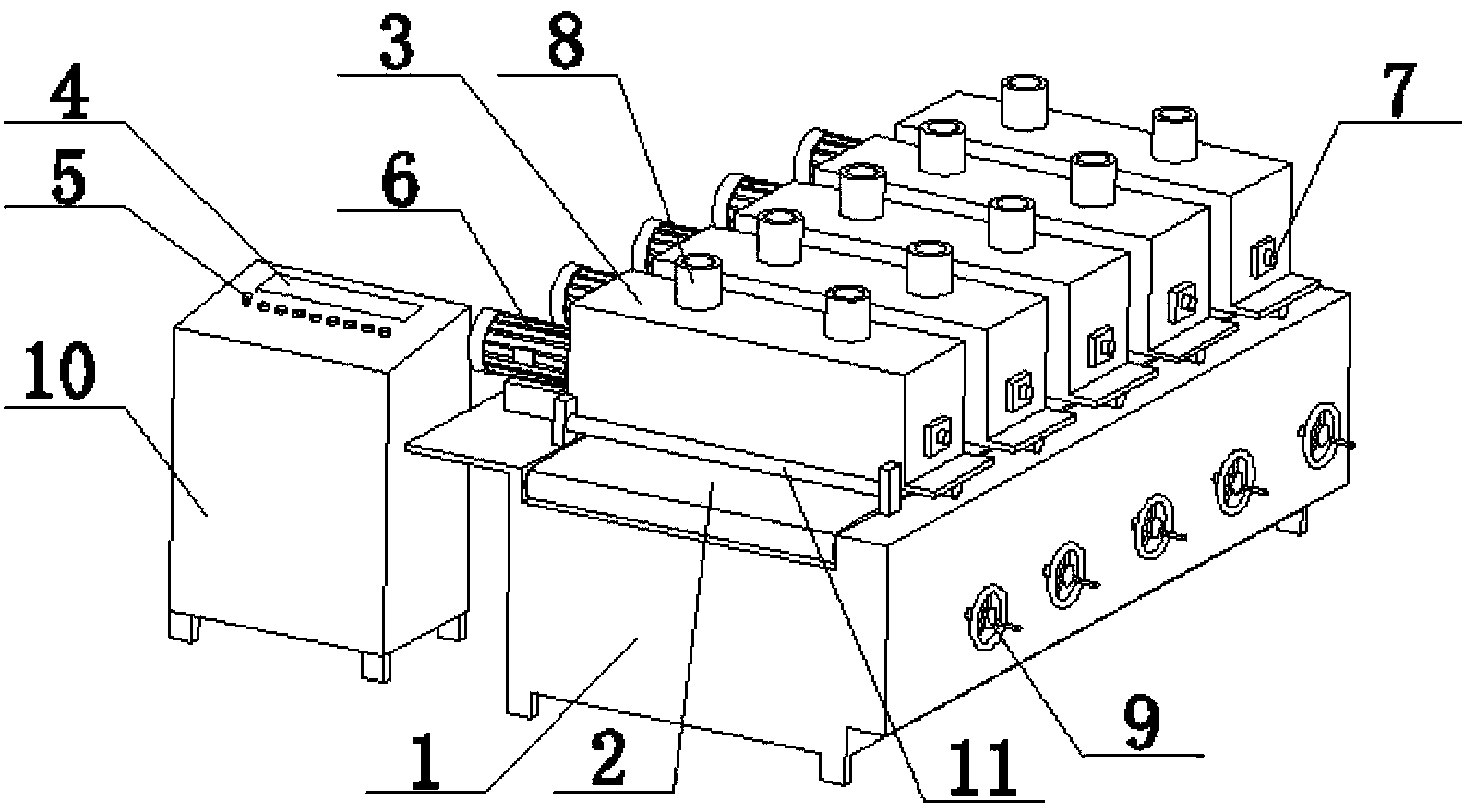
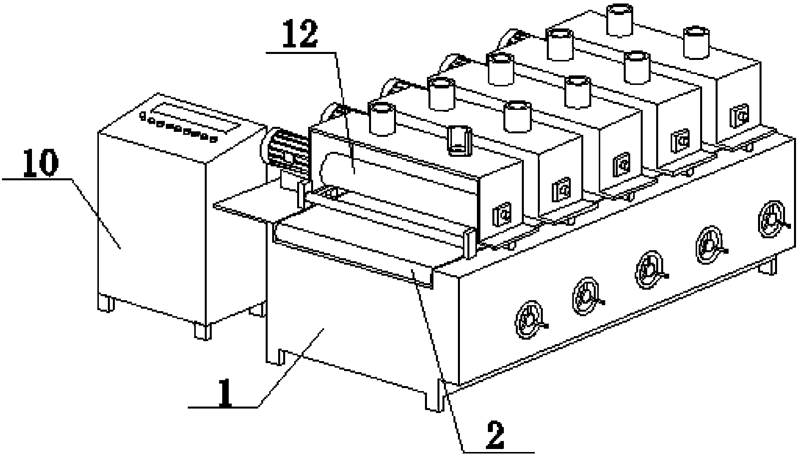
[0018] Embodiment 1 of the present invention: as figure 1 with figure 2 As shown, a plate polishing machine includes a frame 1, a conveying table 2, a polishing chamber 3 and a motor 6. The conveying table 2 is set on the frame 1. The conveying table 2 adopts a full-roller conveyor belt, and the conveying table 2 adopts frequency conversion Speed, the polishing chamber 3 is arranged on the upper end of the transfer table 2, and the frame 1 on one side of each polishing chamber 3 is provided with a separate motor 6, and the other side of each polishing chamber 3 is provided with an installation shaft 7, and the polishing A polishing roller 12 is provided in the chamber 3, and the polishing roller 12 is connected between the motor 6 and the installation shaft 7. The surface of the polishing roller 12 adopts a brush wire with abrasive materials, and the width of the conveying table 2 is 600mm. A power distribution cabinet 10 is arranged on the side, and a digital display 4 is a...

Embodiment 2

[0023] Embodiment 2 of the present invention: as figure 1 with figure 2 As shown, a plate polishing machine includes a frame 1, a conveying table 2, a polishing chamber 3 and a motor 6. The conveying table 2 is set on the frame 1. The conveying table 2 adopts a full-roller conveyor belt, and the conveying table 2 adopts frequency conversion Speed, the polishing chamber 3 is arranged on the upper end of the transfer table 2, and the frame 1 on one side of each polishing chamber 3 is provided with a separate motor 6, and the other side of each polishing chamber 3 is provided with an installation shaft 7, and the polishing A polishing roller 12 is provided in the chamber 3, and the polishing roller 12 is connected between the motor 6 and the installation shaft 7. The surface of the polishing roller 12 adopts a brush wire with abrasive materials, and the width of the conveying table 2 is 650 mm. A power distribution cabinet 10 is arranged on the side, and a digital display 4 is ...

Embodiment 3

[0028] Embodiment 3 of the present invention: as figure 1 with figure 2 As shown, a plate polishing machine includes a frame 1, a conveying table 2, a polishing chamber 3 and a motor 6. The conveying table 2 is set on the frame 1. The conveying table 2 adopts a full-roller conveyor belt, and the conveying table 2 adopts frequency conversion Speed, the polishing chamber 3 is arranged on the upper end of the transfer table 2, and the frame 1 on one side of each polishing chamber 3 is provided with a separate motor 6, and the other side of each polishing chamber 3 is provided with an installation shaft 7, and the polishing A polishing roller 12 is provided in the chamber 3, and the polishing roller 12 is connected between the motor 6 and the installation shaft 7. The surface of the polishing roller 12 adopts a brush wire with abrasive materials, and the width of the conveying table 2 is 650 mm. A power distribution cabinet 10 is arranged on the side, and a digital display 4 is ...


PUM


Abstract

The invention discloses a plate polishing machine which comprises a rack 1, a conveying tabletop 2, polishing rooms 3 and motors 6. The conveying tabletop 2 is arranged on the rack 1, the polishing rooms are arranged at the upper end of the conveying tabletop 2, the position, on one side of each polishing room 3, of the rack 1 is provided with the corresponding independent motor 6, and the other side of each polishing room 3 is provided with an installation shaft 7. Polishing rollers 12 are arranged in the polishing rooms 3, and the polishing rollers 12 are connected between the motors 6 and the installation shafts 7. The width of the conveying tabletop 2 is 600 mm to 700 mm, any side of the rack 1 is provided with a power distribution cabinet 10, and a digital display 4 is arranged on the power distribution cabinet 10. According to the plate polishing machine, the polishing width is increased, the higher machining efficiency is obtained at the same machining speed, a release bearing is used for control, replacing of the polishing rollers is facilitated, meanwhile, the digital display is arranged, and the polishing intensity can be mastered more conveniently.

Description

technical field [0001] The invention relates to a plate polishing machine, which belongs to the technical field of plates. Background technique [0002] Polishing is an essential process in the processing of the plate. After polishing, the plate can be better coated. But polishing machine belongs to the more serious equipment of wearing and tearing, needs frequent replacement for polishing roller, and existing polishing machine all adopts integral bearing design, after polishing roller wears out, it is very inconvenient to replace. Contents of the invention [0003] The purpose of the present invention is to provide a plate polishing machine, which increases the polishing width and obtains higher processing efficiency at the same processing speed. At the same time, it adopts the separation bearing control to facilitate the replacement of polishing rollers. It is equipped with a digital display at the same time. strength. [0004] The technical scheme of the present inven...

Claims


Application Information

Patent Timeline
Patent Type & Authority Applications(China)
IPC IPC(8): B24B29/02B24B55/06
CPCB24B29/005B24B41/00B24B55/06
Inventor 俞金根
Owner HUZHOU NANXUN SHUANGLIN ZHENSEN WOOD PROCESSING FACTORY
Why Eureka
Try Eureka