a digester

A biogas tank and tank body technology, which is applied in the field of biogas tanks, can solve problems such as potential safety hazards of biogas waste, and achieve the effects of convenient replacement of fermentation substances or cleaning of fermentation trays, energy saving, and reduction of leakage or loss.

Active Publication Date: 2016-05-11
JIAXING VOCATIONAL TECHN COLLEGE
View PDF8 Cites 0 Cited by
  • Summary
  • Abstract
  • Description
  • Claims
  • Application Information

AI Technical Summary

Problems solved by technology

[0004] The purpose of the present invention is to solve the above-mentioned problems in the existing technology, and propose a biogas digester, which solves the problems of waste of biogas and potential safety hazards in the prior art when removing biogas slag

Method used


Image

  • a digester
  • a digester
  • a digester

Examples


Embodiment 1

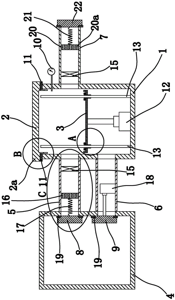
[0043] Such as figure 1 As shown, the biogas digester includes a pool body 1, a sealing cover 2, a fermentation plate 3, a gas storage box 4, an air inlet pipe 5, an air outlet pipe 6, an exhaust pipe 7, an elastic member, a sealing plate one 8, a sealing plate two 9, Lifting device, pressure gauge 10 and other components.

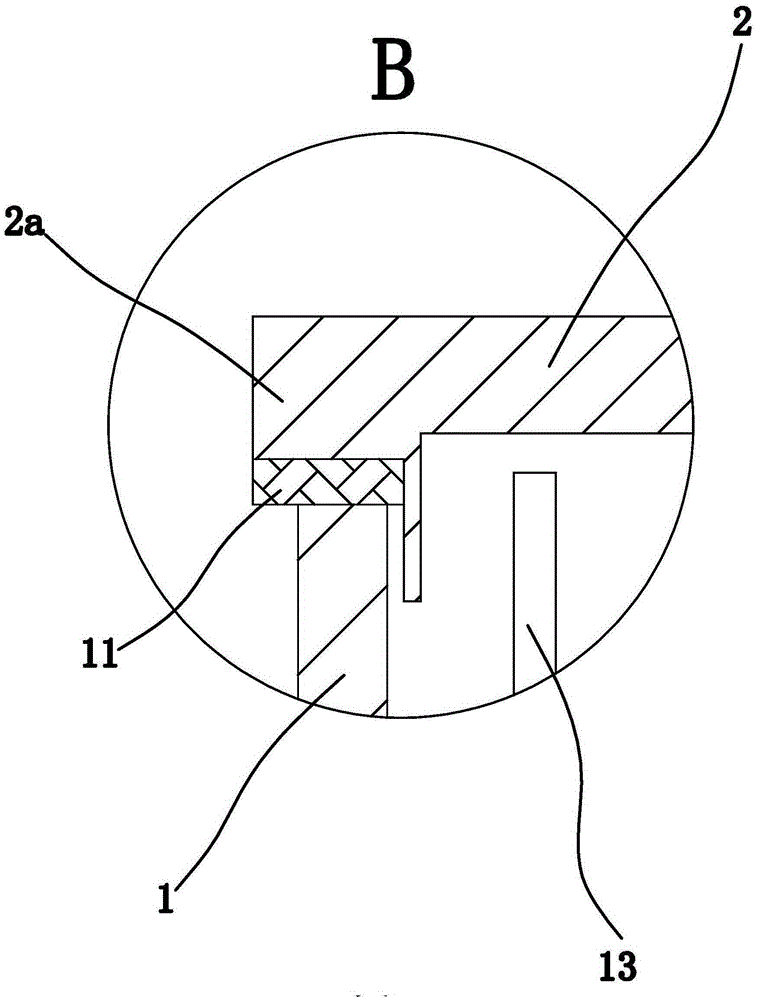
[0044] Wherein, the cell body 1 is cylindrical, and the pressure gauge 10 is fixed on the cell body 1 to measure the air pressure in the cell body 1 . The sealing cover 2 is arranged on the top of the pool body 1 and completely seals the pool body 1 . Specifically, the sealing cover 2 is cylindrical and the weight of the sealing cover 2 is much greater than the buoyancy of the biogas in the pool body 1 to the sealing cover 2, so that the sealing cover 2 will be closely attached to the top surface of the pool body 1 under the effect of weight together, so as to avoid the leakage of biogas.

[0045] Further optimization, a sealing structure is provided be...

Embodiment 2

[0061] The structure and principle of this second embodiment are basically the same as that of the first embodiment, except that the inner side of the sealing cover 2 has a protruding connecting portion, the outer edge of the connecting portion has an annular groove, and the sealing structure includes a The O-shaped sealing ring, and the outer peripheral surface of the O-shaped sealing ring is against the inner wall of the pool body 1 . When the sealing cover 2 is located at the top of the pool body 1, the connecting part located inside the sealing cover 2 is inserted into the pool body 1, and an O-ring is arranged between the outer side wall of the connecting part and the inner side wall of the pool body 1 to improve the sealing The tightness of the connection between the cover 2 and the pool body 1 reduces the probability of biogas leakage; at the same time, the installation of the O-ring is facilitated by setting an annular groove for placing the O-ring.

Embodiment 3

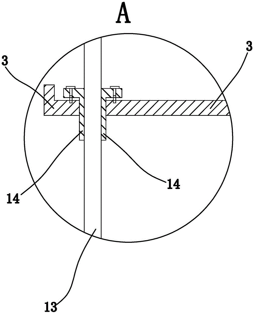
[0063] The structure and principle of the third embodiment are basically the same as those of the first embodiment, except that the lifting device includes a telescopic cylinder, and the telescopic cylinder includes a telescopic piston rod and a cylinder body fixed on the inner bottom wall of the pool body 1, and the telescopic piston rod The end portion is fixedly connected with the fermenting tray 3 by fasteners. When the telescopic cylinder works, the telescopic piston rod can translate up and down relative to the cylinder body, thereby driving the fermentation plate 3 to translate up and down; When cleaning is required, the fasteners can be unscrewed directly and the fermentation tray 3 can be removed from the telescopic piston rod, which has the advantage of being convenient for cleaning the fermentation tray 3; the fasteners can be mechanical fastening parts such as screws and bolts.


PUM


Abstract

The invention provides a biogas digester which is used for solving the problem that waste of biogas is easily caused in the slag removal process in the conventional biogas digester. The biogas digester comprises a gas storage tank and a digester body in which a fermentation disc is arranged, wherein the top of the digester body is connected with a sealing cover; a lifting device which can drive the fermentation disc to translate up and down is arranged at the bottom of the fermentation disc; a gas inlet pipe and a gas outlet pipe are arranged between the gas storage tank and the digester body; a gas suction piece I is arranged in the gas inlet pipe; a sealing plate I and a sealing plate II are arranged in the gas storage tank; an elastic piece through which the sealing plate I has the tendency of sealing the gas inlet pipe is connected to the sealing plate I; a cylinder I through which the sealing plate II seals or opens the gas outlet pipe is connected to the sealing plate II; an exhaust pipe and a pressure gage are connected to the digester body; a gas suction piece II is arranged in the exhaust pipe; a sealing plate III is arranged at the end face of the exhaust pipe; and a spring I through which the sealing plate III has the tendency of sealing the exhaust pipe is arranged between the gas suction piece II and the sealing plate III. The biogas digester disclosed by the invention has the advantages that waste of biogas is avoided during slag removal.

Description

technical field [0001] The invention belongs to the technical field of biogas and relates to a biogas tank. Background technique [0002] Biogas can be used not only as energy for lighting, but also as gas energy for cooking. Since the main raw material for generating biogas comes from crops, it can greatly reduce the consumption of forest resources and coal-fired resources. Therefore, biogas is a popular energy-saving technology that has been popularized and applied in recent years and is widely used in rural areas. [0003] Existing biogas digesters use traditional building materials such as bricks, sand, lime, and cement. Although the method of building a biogas digester is relatively simple, the daily maintenance requirements after completion are very high, and there are many faults during use, for example, leakage Gas is the most common fault in the use of biogas digesters. Often due to poor sealing between the biogas digester and the cover, biogas leaks, resulting in ...

Claims


Application Information

Patent Timeline
Patent Type & Authority Patents(China)
IPC IPC(8): C12M1/107
CPCC12M21/04C12M23/36Y02E50/30
Inventor 钱长根闻敏杰单胜道
Owner JIAXING VOCATIONAL TECHN COLLEGE
Why Eureka
Try Eureka