Intake system for internal combustion engine

A technology for an air intake system and an internal combustion engine, applied in the field of air intake system, can solve problems such as insufficient distribution accuracy, and achieve the effects of suppressing flow, suppressing adverse effects, and suppressing pressure loss

Inactive Publication Date: 2015-01-21
AISIN SEIKI KK
View PDF1 Cites 1 Cited by
  • Summary
  • Abstract
  • Description
  • Claims
  • Application Information

AI Technical Summary

Problems solved by technology

Therefore, according to the known intake system for an internal combustion engine disclosed in Patent Document 1, the distribution accuracy for distributing EGR gas (external air) to each cylinder is insufficient

Method used


Image

  • Intake system for internal combustion engine
  • Intake system for internal combustion engine
  • Intake system for internal combustion engine

Examples


Embodiment Construction

[0042] Embodiments will be described below with reference to the drawings.

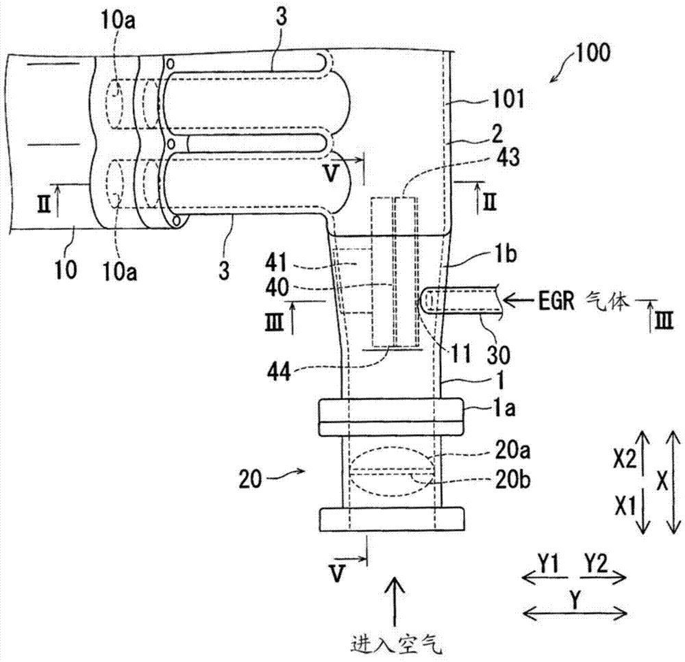
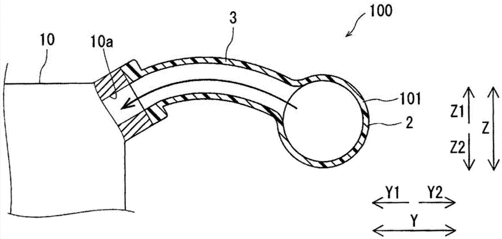
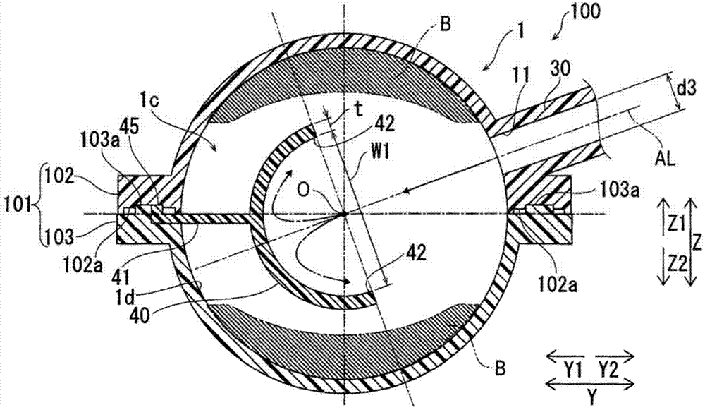
[0043] refer to Figure 1 to Figure 5 , the structure of the intake system 100 of the internal combustion engine will be described.

[0044] An intake system 100 of an internal combustion engine according to the present embodiment corresponds to an intake system of a multi-cylinder engine 10 for an automobile. Such as figure 1 As shown, intake system 100 is configured to receive intake air arriving via an air cleaner and throttle valve 20 . In addition, the intake system 100 is arranged on the upstream side of the multi-cylinder engine 10 to introduce intake air into each cylinder of the multi-cylinder engine 10 . In addition, the intake system 100 is configured to return recirculated exhaust gas (EGR gas or waste recirculated gas) thereinto. EGR gas is an example of external air.

[0045] Such as figure 1 and figure 2 As shown, the engine 10 includes a plurality of intake ports 10a, and one i...


PUM


Abstract

An intake system (100) for an internal combustion engine includes a throttle-side intake tube (1), an external gas introducing port (11) introducing an external gas into at least one of the throttle-side intake tube (1) and a surge tank (2), and a plate portion (40) provided inside the mentioned at least one of the throttle-side intake tube (1) and the surge tank (2) being in communication with the external gas introducing port (11) and in a region on an axis line (AL) of the external gas introducing port (11) at a center portion of a fluid path cross-section having a distance from a vicinity of an outer periphery portion of the fluid path cross-section, the plate portion (40) restraining the external gas that is introduced from the external gas introducing port (11) from flowing to the vicinity of the outer periphery portion of the fluid path cross-section by blocking the external gas at the center portion of the fluid path cross-section.

Description

technical field [0001] The present invention generally relates to an air intake system for an internal combustion engine. Background technique [0002] A known intake system for an internal combustion engine for introducing external air into a throttle side intake pipe is disclosed in JP2010-144669A (ie, hereinafter referred to as Patent Document 1). [0003] The intake system for an internal combustion engine disclosed in Patent Document 1 includes: an intake pipe (throttle side intake pipe) that introduces intake air from a throttle valve to a main pipe portion (surge tank); To the EGR pipe (exhaust gas recirculation pipe) inside the intake pipe. According to the intake system disclosed in Patent Document 1, the outlet portion of the EGR pipe arranged to protrude into the intake pipe is inclined to face the main pipe portion side (downstream side). Therefore, the outflow direction of the EGR gas introduced from the EGR pipe is toward the downstream side so that the conce...

Claims


Application Information

Patent Timeline
Patent Type & Authority Applications(China)
IPC IPC(8): F02M25/07
CPCF02M35/10091F02M35/10222F02M35/10262F02M25/0722F02M35/10118F02M35/104F02M26/19Y02T10/12
Inventor 伊藤笃史森圭太郎
Owner AISIN SEIKI KK
Why Eureka
Try Eureka