
Small-diameter tube nondestructive testing method based on phased array ultrasonic flaw detector

A non-destructive testing and ultrasonic technology, which is applied in the direction of using sound wave/ultrasonic wave/infrasonic wave to analyze solids, etc. It can solve the problems of human injury, installation time, and low sensitivity, and achieve the effect of reducing detection cost, avoiding repeated detection, and improving debugging accuracy.

Active Publication Date: 2015-01-21
中能建建筑集团有限公司 +2
View PDF3 Cites 15 Cited by
  • Summary
  • Abstract
  • Description
  • Claims
  • Application Information

AI Technical Summary

Problems solved by technology

However, the use of ray detection or conventional ultrasonic detection has limitations. First, the use of ray detection will cause damage to the human body due to the radiation. The two sides of the small-diameter tube almost become blind spots for radiation detection. Although the use of large-dose gamma source detection will have certain effects, it is not worth the gain compared with the pollution of the radiation source to the surrounding environment and the damage to the detection personnel. Moreover, When performing radiographic inspection, it is necessary to clear the installation personnel at multiple operating points in the installation space, which takes up installation time and affects the progress of the installation and construction project; secondly, conventional ultrasonic inspection is used. Although it is sensitive to area defects, its detection The ability of volume defects is poor, and the defect display is not intuitive, the detection method is single, the sensitivity is low, and the detection results are greatly affected by human
It can be seen from the above that due to the shortcomings of ray detection and conventional ultrasonic detection technology, it often brings a lot of inconvenience during the construction process.

Method used


Image

  • Small-diameter tube nondestructive testing method based on phased array ultrasonic flaw detector

Examples


Embodiment Construction

[0025] The phased array ultrasonic flaw detector includes probe, scanning frame, wedges, host, battery, etc. When the phased array ultrasonic flaw detector is used to detect the workpiece, the probe is fixed on the scanning frame, and the wedge is fixed at the front end of the probe. For different specifications of the workpiece, different specifications of the wedges are selected.

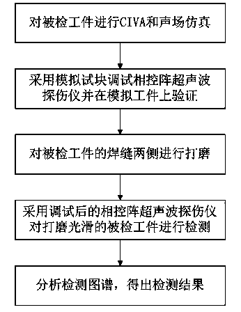
[0026] Such as figure 1 As shown, a small-diameter tube non-destructive testing method based on phased array ultrasonic flaw detector includes the following steps:

[0027] S1. Before on-site inspection, perform CIVA and sound field simulation for the specifications of the inspected workpiece (thickness, weld diameter, etc.), and input the simulation results into the phased array ultrasonic flaw detector.

[0028] In the simulation, the input parameters include the groove angle, thickness, pipe diameter, weld reinforcement, and gap of the inspected workpiece, and the output parameters include the ultra...


PUM


Abstract

The invention provides a small-diameter tube nondestructive testing method based on a phased array ultrasonic flaw detector. The small-diameter tube nondestructive testing method comprises the following steps: carrying out CIVA and sound field simulation on a detected workpiece; debugging the phased array ultrasonic flaw detector by a simulation test block and verifying on a simulated workpiece; grinding two sides of a welding seam of the detected workpiece, detecting the detected workpiece ground smoothly by the debugged phased array ultrasonic flaw detector; and analyzing the detection graph to obtain a detection result. The method can perform CIVA and sound field simulation on the detected workpiece before field detection, and adopts an appropriate comparison test block and the simulation workpiece for debugging the phased array ultrasonic flaw detector; the method adopts different scanning modes according to the different thicknesses of the simulation workpieces in a debugging process, can improve the debugging precision, can improve the field detection sensitivity, can prevent repeated detection, saves the detection time and reduces the detection cost.

Description

Technical field [0001] The invention relates to the technical field of non-destructive testing, in particular to a small-diameter tube non-destructive testing method based on a phased array ultrasonic flaw detector. [0002] Background technique [0003] At present, in the domestic electric power (nuclear power, thermal power) installation projects, small-caliber pipes are densely distributed. During the installation process, they are in a three-dimensional three-dimensional space, and the cross-working points are wide. Generally, 100% radiographic or conventional pipe welds are required Ultrasonic non-destructive testing to ensure the quality of installation. However, the use of radiographic testing or conventional ultrasonic testing has limitations. First, the use of radiographic testing, due to the radiation of the rays, will cause harm to the human body, especially in the ultra-supercritical unit, the wall of the small diameter tube is getting thicker and thicker. Both sides ...

Claims


Application Information

Patent Timeline
Patent Type & Authority Applications(China)
IPC IPC(8): G01N29/04
Inventor 余新海孙磊樊传琦朱琪单立春姜学平刘礼良杨齐董亮亮章雅林高超涂少华吴松
Owner 中能建建筑集团有限公司
Learn More