Partial optical fiber discharge detecting system

A partial discharge detection and photodetector technology, applied in the direction of testing dielectric strength, etc., can solve the problems of low positioning accuracy, high cost, low sensitivity, etc.

Active Publication Date: 2015-01-21
BEIJING INST OF AEROSPACE CONTROL DEVICES
View PDF4 Cites 19 Cited by
  • Summary
  • Abstract
  • Description
  • Claims
  • Application Information

AI Technical Summary

Problems solved by technology

The test frequency f of the pulse current method is low (generally f<1MHz), and the frequency band is narrow. It is easily affected by external interference and noise when applied to on-site measurement, and its anti-interference ability is poor. Therefore, this method is only suitable for use in laboratories; The frequency method has many practical applications, but its cost is expensive, the positioning accuracy is not high (±0.1m), and the electromagnetic pulse signal strength of the partial discharge re

Method used


Image

  • Partial optical fiber discharge detecting system
  • Partial optical fiber discharge detecting system
  • Partial optical fiber discharge detecting system

Examples


Embodiment Construction

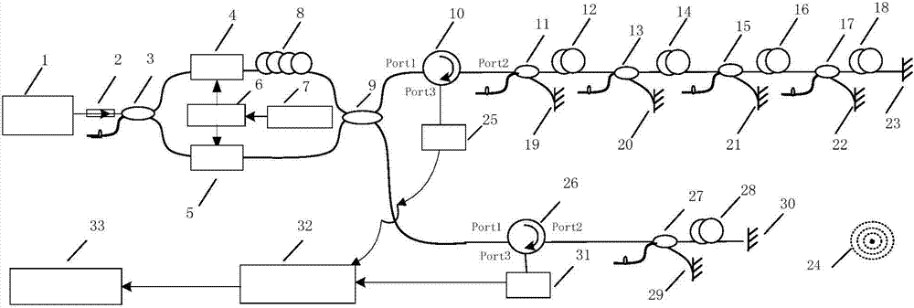
[0037] Such as figure 2 As shown, it is a block diagram of the system composition of the present invention, including a narrow-band light source 1, an optical fiber isolator 2, an optical fiber coupler 3, an acousto-optic modulator 4, an acousto-optic modulator 5, a synchronous driving source 6, a signal generator 7, an optical fiber extension Time ring 8, fiber optic coupler 9, fiber optic circulator 10, fiber optic coupler 11, fiber optic delay loop 12, fiber optic coupler 13, fiber optic delay loop 14, fiber optic coupler 15, fiber optic delay loop 16, fiber optic coupler 17. Optical fiber delay loop 18, Faraday rotating mirror 19, Faraday rotating mirror 20, Faraday rotating mirror 21, Faraday rotating mirror 22, Faraday rotating mirror 23, partial discharge signal source 24, photodetector 25, fiber optic circulator 26, optical fiber Coupler 27, optical fiber delay ring 28, Faraday rotating mirror 29, Faraday rotating mirror 30, photoelectric detector 31, high-speed signal...


PUM

PropertyMeasurementUnit
Isolationaaaaaaaaaa
Insertion lossaaaaaaaaaa
Ratioaaaaaaaaaa

Abstract

A partial optical fiber discharge detecting system comprises a light source, an acoustic-optic modulation device, a sensing light path and a demodulating system. Frequency shifting and delaying are carried out on light emitted by the light source through the acoustic-optic modulation device, and only two paths of light with the same optical path can interfere in the sensing light path and a reference light path. When partial discharge signals occur outside, the generated sound waves act on the sensing light path, the phase position of the interference signals changes, and the related information (intensity, position and the like) of outside partial discharge signals can be obtained by demodulating the variable quantity. Compared with traditional electromagnetic sensing and piezoelectric sensing, optical fiber sensing is insulated from electromagnetism essentially, the sensing optical fiber can be arranged in insulating oil of a transformer, the sensitivity for detecting the partial discharge signals is further improved, multiplexing can be formed easily, and the partial discharge signals can be precisely positioned.

Description

technical field [0001] The invention belongs to the field of power system automation, in particular to an optical fiber partial discharge detection system. Background technique [0002] With the development of the national economy, the requirements for the reliable operation of the power system are getting higher and higher. Electrical equipment is the basic component of the power system. Once an accident occurs, it will not only affect adjacent equipment, but also cause heavy economic losses to users. Large-scale electrical equipment mostly uses various organic synthetic insulating materials such as mineral oil, insulating paper or epoxy resin to form a composite structure. A large number of data show that insulation failure is the main cause of electrical equipment failure. [0003] Partial discharge is not only the main cause of insulation failure, but also an important symptom and manifestation of insulation degradation, which is closely related to the degradation and b...

Claims


Application Information

Patent Timeline
IPC IPC(8): G01R31/12
Inventor 路书祥涂万郝良彬何哲玺于文鹏王学锋孔令兵
Owner BEIJING INST OF AEROSPACE CONTROL DEVICES
Why Eureka
Try Eureka