Torsion ring for microwave device testing

A microwave device and torsion ring technology, applied in the field of semiconductor device testing, can solve the problems of inconvenient operation, affecting the accuracy of test results, peripheral metal falling off, etc., to improve accuracy and stability, achieve non-destructive testing, and increase friction. Effect

Active Publication Date: 2015-01-21
THE 13TH RES INST OF CHINA ELECTRONICS TECH GRP CORP
View PDF5 Cites 0 Cited by
  • Summary
  • Abstract
  • Description
  • Claims
  • Application Information

AI Technical Summary

Problems solved by technology

Since the metal wrench is in hard contact with the periphery of the coaxial connector, a layer of metal is usually plated on the periphery of the coaxial connector, which may easily cause the peripheral metal to fall off and affect the indicators such as the differential loss of the coaxial connector.
At the same time, if the force is too strong, it will be difficult to separate the coaxial connector from the test system, which will easily cause deformation of the coaxial connector
If the device needs to be tested many times, frequent use of soldering iron will reduce the reliability of the test fixture test system and cause mechanical damage to the device terminals
[0004] In some places where the space is small, metal wrench cannot be used, and it can only be operated by hand, which is very inconvenient. At the same time, due to the limited force of the hand, the coaxial connector of the test fixture is not tightly connected with the coaxial connector of the test system, which affects the accuracy of the test results.
[0005] Microwave devices are devices that amplify microwave signals. When performing microwave testing of devices, a certain DC operating voltage and microwave input signals, such as 10dBm signals, must be applied to the device using a test fixture to obtain device noise, gain, power, and efficiency. If the coaxial connector of the test fixture is not tightly connected to the coaxial connector of the test system, the noise figure of the device will be greater than the real value, and the test values ​​of gain, power and efficiency will be lower than the real value.

Method used


Image

  • Torsion ring for microwave device testing
  • Torsion ring for microwave device testing
  • Torsion ring for microwave device testing

Examples


Embodiment

[0025] The invention is applied to GaN HEMT and SiC MESFET microwave device testing. Specific embodiments are as follows.

[0026] Device and test description: 1) Gate width: 27 mm; 2) Test parameters: saturation current, output power at 3.2 GHz, gain and efficiency.

[0027] The present invention is applied to GaN HEMT and SiC MESFET microwave device testing, including the following steps:

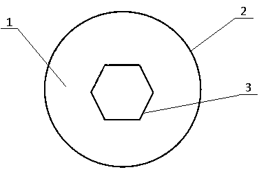
[0028] 1) According to the external dimensions of the input and output terminals of the test fixture (in this case, SMA male), use PTFE material to design the internal structure of the twist ring;

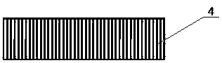
[0029] 2) Design the peripheral structure of the torsion ring, using polytetrafluoroethylene material to make the torsion ring;

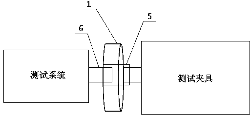
[0030] 3) Use a twist ring to connect the input and output terminals of the test fixture (in this case, SMA coaxial male connector terminal 5) to the test system coaxial connector connection (in this case, SMA coaxial female connector terminal 6);

[0031] 4) Tes...


PUM


Abstract

The invention discloses a torsion ring for microwave device testing, and relates to the technical field of semiconductor device testing. The cross section of the outer ring wall of the torsion ring is circular. The cross section of the inner ring wall of the torsion ring is hexagonal. The inner ring wall and the outer ring wall of the torsion ring are matched with microwave device testing clamp input and output coaxial connector terminals in appearance and size. The torsion ring is made of polytetrafluoroethylene materials. Due to the fact that the polytetrafluoroethylene torsion ring with a reticulate structure is adopted, the problem that a testing clamp is not in tight connection in the testing process is successfully solved, the device testing stability, accuracy and non-destruction are ensured, the manufacturing cost is low, the torsion ring is easy to obtain, and it is ensured that related scientific research and production can be smoothly carried out.

Description

technical field [0001] The invention relates to the technical field of semiconductor device testing. Background technique [0002] Microwave devices can be produced based on semiconductor materials. In order to verify the DC and microwave characteristics of microwave devices, they need to be tested. The test process requires the use of test fixtures, and the input and output terminals of the test fixture are either connected to the load or connected to the test system to realize DC and microwave testing. Several important indicators of device testing are test stability, accuracy, and non-destructiveness. Non-destructive means that the test process cannot cause damage to the fixture. If the input and output terminals of the test fixture are not tightly connected to the system, it is easy to cause inaccurate test parameters and affect the test accuracy. [0003] In common tests, the input and output terminals of the test fixture are in the form of coaxial connectors, and the...

Claims


Application Information

Patent Timeline
Patent Type & Authority Applications(China)
IPC IPC(8): G01R31/26
Inventor 李亮默江辉崔玉兴付兴昌蔡树军杨克武
Owner THE 13TH RES INST OF CHINA ELECTRONICS TECH GRP CORP
Why Eureka
Try Eureka