Dual-mode composite infrared electric control liquid crystal micro-lens array chip

A technology of liquid crystal microlenses and array chips, applied in instruments, optics, static indicators, etc., can solve problems such as slow response, large inertia, and invariance of optical performance, and achieve flexible control methods, wide variation ranges, and high control accuracy Effect

Active Publication Date: 2015-01-21
HUAZHONG UNIV OF SCI & TECH
View PDF6 Cites 6 Cited by
  • Summary
  • Abstract
  • Description
  • Claims
  • Application Information

AI Technical Summary

Problems solved by technology

[0003] Based on the matching coupling of conventional converging and diverging microlens arrays, the defects of the technical method of functionalized beam shaping and beam transformation are mainly manifested in the following aspects: Invariance, only by changing the spacing or relative position of the microlens array to construct a specific beam shape and light energy transport mode; Fine adjustment ability; (3) Adjusting the position arrangement between the microlens arrays through mechanical movement needs to be carried out in a specific order, the response is slow, the state transition takes a long time, and the inertia is large, and it needs to be matched with complex auxiliary drive control devices. (4) It is difficult to flexibly access the optical path or couple or even integrate with other infrared optical optoelectronic structures

Method used


Image

  • Dual-mode composite infrared electric control liquid crystal micro-lens array chip
  • Dual-mode composite infrared electric control liquid crystal micro-lens array chip
  • Dual-mode composite infrared electric control liquid crystal micro-lens array chip

Examples


Embodiment Construction

[0026] In order to make the object, technical solution and advantages of the present invention clearer, the present invention will be further described in detail below in conjunction with the accompanying drawings and embodiments. It should be understood that the specific embodiments described here are only used to explain the present invention, not to limit the present invention. In addition, the technical features involved in the various embodiments of the present invention described below can be combined with each other as long as they do not constitute a conflict with each other.

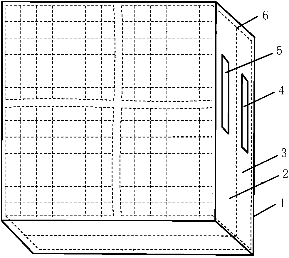
[0027] like figure 1 As shown, the dual-mode composite infrared electronically controlled liquid crystal microlens array chip of the present invention includes: a chip housing 1, an electronically controlled astigmatism liquid crystal microlens array 2, an electronically controlled light concentrating liquid crystal microlens array 3, and a first drive signal input port 4 and the second drive c...


PUM


Abstract

The invention discloses a dual-mode composite infrared electric control liquid crystal micro-lens array chip which comprises a chip shell, an electric control light divergence liquid crystal micro-lens array and an electric control light condensation liquid crystal micro-lens array. The electric control light divergence liquid crystal micro-lens array and the electric control light condensation liquid crystal micro-lens array are in cascade coupling connection to form a dual-mode composite electronic speed controller framework. The electric control light divergence liquid crystal micro-lens array and the electric control light condensation liquid crystal micro-lens array are both arranged inside the chip shell, are tightly attached to each other and are connected with the chip shell. The optical axis of the electric control light divergence liquid crystal micro-lens array coincides with the optical axis of the electric control light condensation liquid crystal micro-lens array. The light incident plane of the electric control light divergence liquid crystal micro-lens array and the light emergent plane of the electric control light condensation liquid crystal micro-lens array are exposed out through an opening in the top face of the chip shell and an opening in the bottom face of the chip shell respectively. The dual-mode composite infrared electric control liquid crystal micro-lens array chip is compact in structure, capable of being used for forming various light beam forms, better in light field adaptability compared with a conventional electric control liquid crystal micro lens, high in control precision and capable of being coupled with a conventional infrared optics and optoelectronic mechanical structure easily.

Description

technical field [0001] The invention belongs to the technical field of infrared beam precision measurement and control, and more specifically relates to a dual-mode composite infrared electronically controlled liquid crystal microlens array chip. Background technique [0002] In recent years, based on the coupling and even integration of light converging and light diverging microlens arrays, the technology of functionalized beam transformation has developed rapidly and has been applied in many fields. Typically constructed by interlacing movement between converging microlens arrays in a cascaded configuration, smart light field scanners and laser beam scanning projectors; coupling converging and diverging microlens arrays to reduce aberrations, adjust Converging and diverging microlens array spacing to adjust the field of view, focal length, focal spot size and focal depth; orderly adjustment of the distribution shape and spacing of staggered multi-microlens arrays, smart hi...

Claims


Application Information

Patent Timeline
Patent Type & Authority Applications(China)
IPC IPC(8): G02F1/29G02F1/1343G02F1/133G01J3/12
CPCG02F1/13306G02F1/134309G02F1/29
Inventor 张新宇罗俊佟庆雷宇桑红石张天序谢长生
Owner HUAZHONG UNIV OF SCI & TECH
Why Eureka
Try Eureka