
Method for forming a shallow trench isolation structure

A technology of isolation structure and shallow trench, which is applied in the direction of electrical components, semiconductor/solid-state device manufacturing, circuits, etc., can solve the problems of shallow trench isolation structure breakdown and leakage current increase, and avoid breakdown and narrow-width effect , Reduce leakage current, avoid the effect of stress concentration

Active Publication Date: 2015-01-21
SEMICON MFG INT (SHANGHAI) CORP
View PDF6 Cites 4 Cited by
  • Summary
  • Abstract
  • Description
  • Claims
  • Application Information

AI Technical Summary

Problems solved by technology

When the current is passed through the semiconductor device, the high electric field is easy to concentrate at the defect position, resulting in increased leakage current, breakdown of the shallow trench isolation structure, and narrow width effect (Narrow Width Effect)

Method used


Image

  • Method for forming a shallow trench isolation structure
  • Method for forming a shallow trench isolation structure
  • Method for forming a shallow trench isolation structure

Examples


Embodiment Construction

[0035] Through creative work, the present invention provides a new method for forming a shallow trench isolation structure, which makes the sharp chamfer at the top of the sidewall of the shallow trench smooth.

[0036] In order to make the above objects, features and advantages of the present invention more clearly understood, the specific embodiments of the present invention will be described in detail below with reference to the accompanying drawings.

[0037] refer to Figure 5 , a substrate 300 is provided, a silicon oxide layer 301 is formed on the substrate 300 , and a silicon nitride layer 302 is formed on the silicon oxide layer 301 .

[0038] Specifically, first, a chemical vapor deposition or thermal oxidation growth process is used to form a silicon oxide layer 301 on the upper surface of the substrate 300, and the silicon oxide layer 301 is used to isolate the substrate 300 to prevent the subsequent process from causing pollution to the substrate 300, and It acts...


PUM


Abstract

A method for forming a shallow trench isolation structure includes: providing a substrate; etching the substrate to form a shallow trench, forming a sharp corner at the top sidewall of the shallow trench; forming dielectric material at the shallow trench; then performing annealing treatment in an inert gas atmosphere to smooth the sharp corner, wherein the molecular mass of the gas in the gas atmosphere is greater than or equal to that of argon gas. Annealing treatment changes sharp corner into a rounded angle, and the rounded angle can avoid stress concentrating. When a current passing through a semiconductor device, a high electric field is not concentrated in the rounded position, thereby decreasing leakage current, avoiding breakdown and narrow width effect of the shallow trench isolation structure.

Description

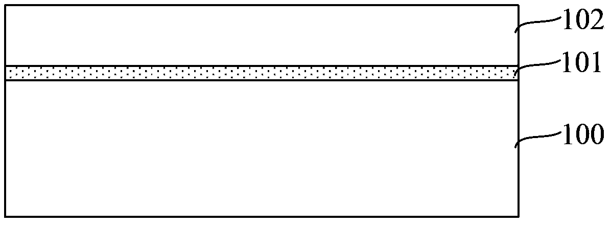
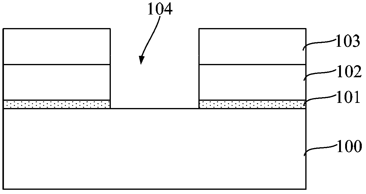
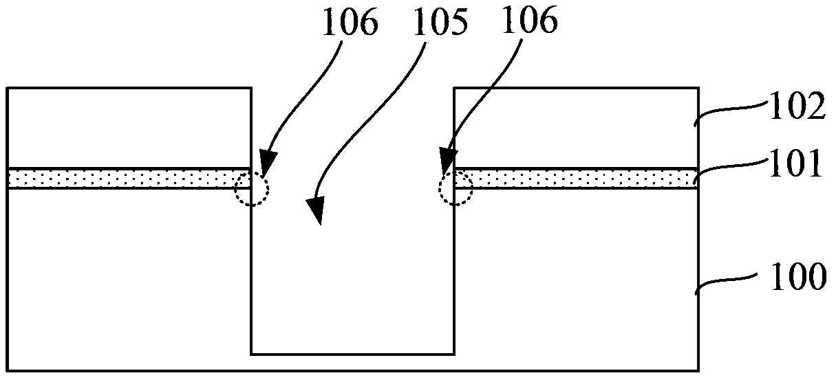
technical field [0001] The present invention relates to the field of semiconductor technology, and in particular, to a method for forming a shallow trench isolation structure. Background technique [0002] In the prior art, semiconductor device isolation using Shallow Trench Isolation (STI) technology has become a conventional technology. [0003] Figure 1 ~ Figure 4 It is a schematic cross-sectional structure diagram of a method for manufacturing a shallow trench isolation structure in the prior art. refer to figure 1 , a silicon oxide layer 101 and a silicon nitride layer 102 located on the silicon oxide layer 101 are formed on the substrate 100 . refer to figure 2 , a patterned photoresist layer 103 is formed on the silicon nitride layer, and the patterned photoresist layer 103 is used as a mask to etch the silicon nitride layer and the silicon oxide layer. An opening 104 is formed therein, and the opening 104 exposes the surface of the substrate 100 . refer to ...

Claims


Application Information

Patent Timeline
IPC IPC(8): H01L21/762
CPCH01L21/76224H01L21/76232
Inventor 张海洋张翼英
Owner SEMICON MFG INT (SHANGHAI) CORP
Learn More