
Bandwidth-adjustable passive multiphase filter circuit

A polyphase filter and filter technology, applied in electrical components, phase-shifting networks, multi-terminal-pairing networks, etc., can solve the problems of complex circuit structure and large chip area, and achieve the effect of simplifying the circuit structure and reducing the chip area.

Inactive Publication Date: 2015-01-21
SHAANXI BEIDOU HENGTONG INFORMATION TECH
View PDF4 Cites 3 Cited by
  • Summary
  • Abstract
  • Description
  • Claims
  • Application Information

AI Technical Summary

Problems solved by technology

Because multiple passive polyphase filters are integrated inside the chip, the circuit structure is complex and the chip area is large

Method used


Image

  • Bandwidth-adjustable passive multiphase filter circuit

Examples


Embodiment Construction

[0012] The present invention will be described in detail below in conjunction with the accompanying drawings.

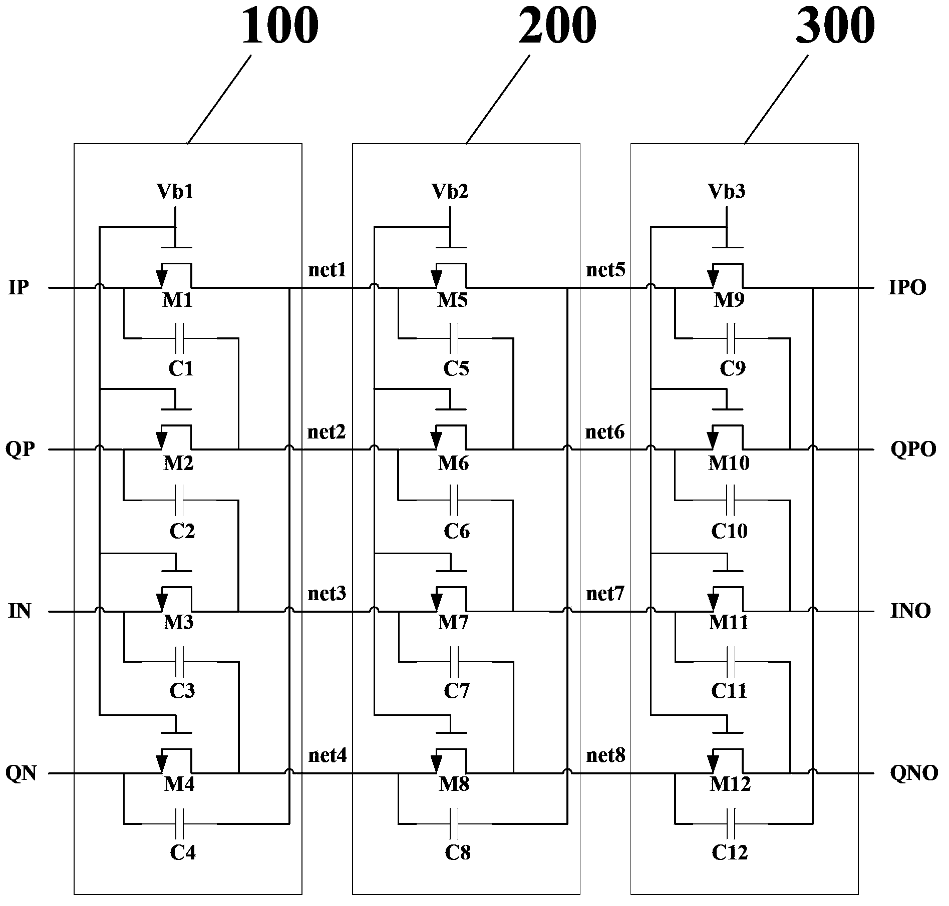
[0013] see figure 1 , a passive polyphase filter circuit with adjustable bandwidth includes a first-order filter 100, a second-order filter 200 and a third-order filter 300, and the three filters are combined to form a third-order passive polyphase filter circuit phase filter.

[0014] The first-order filter 100 includes: a first MOS transistor M1, a second MOS transistor M2, a third MOS transistor M3, a fourth MOS transistor M4, a first capacitor C1, a second capacitor C2, a third capacitor C3 and a first capacitor C3. Four capacitors C4.

[0015] The drain of the first MOS transistor M1 is connected to the non-inverting positive output terminal net1 of the first-order filter 100, the gate of the first MOS transistor M1 is connected to the first bias voltage Vb1, and the source of the first MOS transistor M1 Connected to the non-inverting positive input terminal ...


PUM


Abstract

The invention discloses a bandwidth-adjustable passive multiphase filter circuit. The bandwidth-adjustable passive multiphase filter circuit comprises a first-order filter, a second-order filter and a third-order filter which are connected in sequence, wherein the three filters are combined into a three-order passive multiphase filter. According to the bandwidth-adjustable passive multiphase filter circuit, four paths of orthogonal differential signals are received through four ports, namely, an in-phase forward input end, an orthogonal forward input end, an in-phase backward input end and an orthogonal backward input end; output ports comprise an in-phase forward output end, an orthogonal forward output end, an in-phase backward output end and an orthogonal backward output end; and the turn-on resistance of an MOS (Metal Oxide Semiconductor) transistor can be changed by adjusting a first bias voltage, a second bias voltage and a third bias voltage, so that the bandwidth of the passive multiphase filter is changed. Compared with the prior art, the bandwidth-adjustable passive multiphase filter circuit has the advantages and effects that the circuit structure is simplified, and the chip area is reduced.

Description

technical field [0001] The invention relates to the technical field of radio frequency integrated circuits, and relates to a passive polyphase filter circuit with adjustable bandwidth. Background technique [0002] With the development of integrated circuit technology, higher and higher requirements are put forward for RF receivers. RF front-end chips are required to receive RF signals at multiple frequency points. RF signals at different frequency points often have different signal bandwidths. Therefore, it is necessary to Use image rejection filters with different bandwidths. The core part of the image frequency suppression filter is a passive polyphase filter, and passive polyphase filters with different bandwidths need to be designed for signals with different bandwidths. [0003] Traditional RF front-end chips often integrate multiple passive polyphase filters. According to different application environments, one of the passive polyphase filters is selected for use acc...

Claims


Application Information

Patent Timeline
Patent Type & Authority Applications(China)
IPC IPC(8): H03H7/00
CPCH03H7/20H03H11/20H03H11/22H03H7/21
Inventor 申向顺李波李卫斌王红丽姜恩春
Owner SHAANXI BEIDOU HENGTONG INFORMATION TECH
Learn More