Straw cutting, throwing and returning machine for combined harvester and mounting method of straw cutting, throwing and returning machine

A combine harvester and straw technology, which is applied in the fields of harvesters, agricultural machinery and implements, applications, etc., can solve problems such as affecting life and traffic safety, reducing effective utilization, and wasting resources and the environment, so as to reduce the number of operations and solve problems such as The problem of straw burning and the effect of protecting the environment

Active Publication Date: 2015-01-28
金湖县兴鹏机械制造有限公司
View PDF13 Cites 8 Cited by
  • Summary
  • Abstract
  • Description
  • Claims
  • Application Information

AI Technical Summary

Problems solved by technology

[0003] At present, the effective utilization rate of crop stalks such as rice, wheat and corn has dropped sharply, and a large amount of stalks have been discarded or burned, which has seriously caused waste of resources and environmental pollution, directly affecting people's lives and traffic safety, and has already aroused the attention of leaders at all levels. and the concern of the broad masses of the people, therefore, it is urgent to find a way out of crop straw
[0004] It is a simple, quick and effective method to return crop straw to the field, but the straw crushing and returning machine currently popularized in my country has problems such as large workload, poor crushing effect, low work efficiency and poor use efficiency, etc. To meet the needs of straw and high stubble crushing and returning to the field after the operation of the combine harvester, therefore, it is urgent to research and develop a new type of straw chopping and throwing returning machine

Method used


Image

  • Straw cutting, throwing and returning machine for combined harvester and mounting method of straw cutting, throwing and returning machine
  • Straw cutting, throwing and returning machine for combined harvester and mounting method of straw cutting, throwing and returning machine

Examples


Embodiment 1

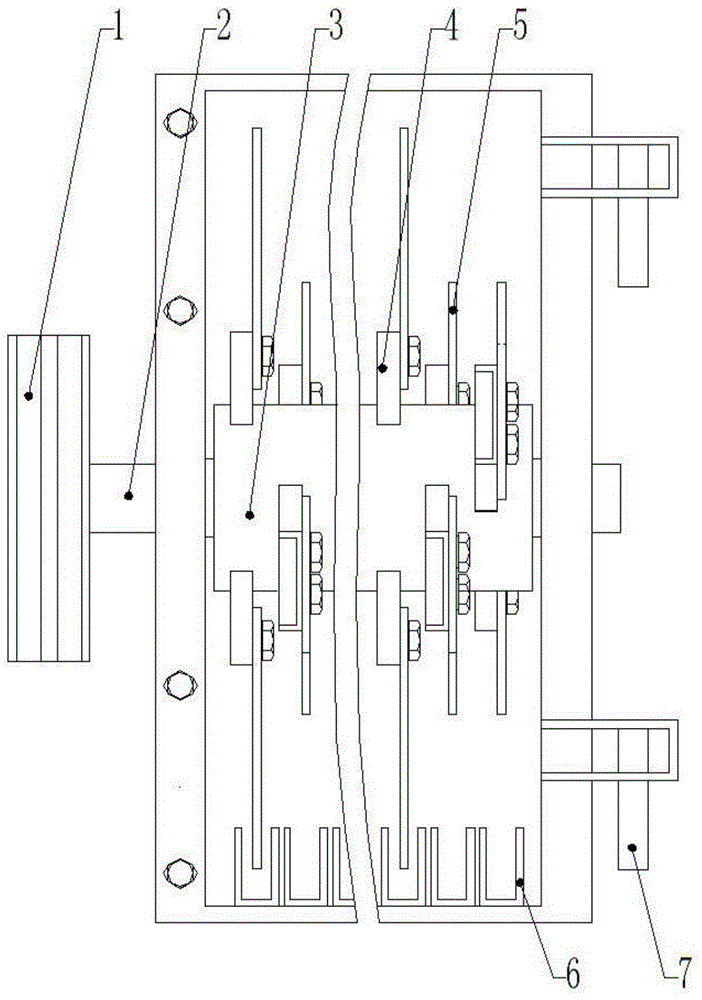
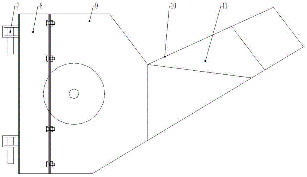
[0024] This embodiment provides a straw chopping, throwing, and returning machine for combine harvesters. The straw chopping, throwing, and returning machine for combine harvesters in this embodiment is used in conjunction with a wheeled combine harvester. If the structure is as follows figure 1 , figure 2 As shown, it includes a pulley 1, a cutter shaft 2 and a protective casing. The pulley 1 is fixed on the end of the cutter shaft 2 through a key connection. The cutter shaft 2 traverses the protective casing and is fixed inside the protective casing. It also includes a cutter roller The assembly 3 and the fixed knife group 6, the knife roller assembly 3 is connected and fixed with the casing 9 through bearings and flanges, and the knife roller assembly 3 includes the knife magazine 4 and the chopping knife 5, and the knife roller assembly 3 is cylindrical structure, the chopping knife 5 is a double-edged trapezoidal blade, one end of which is installed on the knife magazine...

Embodiment 2

[0028] This embodiment provides a straw chopping, throwing, and field returning machine for combine harvesters. The straw chopping, throwing, and field returning machine for combine harvesters in this embodiment is used in conjunction with Chery combine harvesters. If the structure is as follows figure 1 , figure 2 As shown, it includes a pulley 1, a cutter shaft 2 and a protective casing. The pulley 1 is fixed on the end of the cutter shaft 2 through a key connection. The cutter shaft 2 traverses the protective casing and is fixed inside the protective casing. It also includes a cutter roller The assembly 3 and the fixed knife group 6, the knife roller assembly 3 is connected and fixed with the casing 9 through bearings and flanges, and the knife roller assembly 3 includes the knife magazine 4 and the chopping knife 5, and the knife roller assembly 3 is cylindrical structure, the chopping knife 5 is a double-edged trapezoidal blade, one end of which is installed on the knife...

Embodiment 3

[0032] This embodiment provides a straw chopping, throwing and returning machine for a combine harvester. The straw cutting and throwing returning machine for a combine harvester in this embodiment is used in conjunction with a Yanmar combine harvester. Its structure is as follows figure 1 , figure 2As shown, it includes a pulley 1, a cutter shaft 2 and a protective casing. The pulley 1 is fixed on the end of the cutter shaft 2 through a key connection. The cutter shaft 2 traverses the protective casing and is fixed inside the protective casing. It also includes a cutter roller The assembly 3 and the fixed knife group 6, the knife roller assembly 3 is connected and fixed with the casing 9 through bearings and flanges, and the knife roller assembly 3 includes the knife magazine 4 and the chopping knife 5, and the knife roller assembly 3 is cylindrical structure, the chopping knife 5 is a double-edged trapezoidal blade, one end of which is installed on the knife magazine 4 thro...


PUM


Abstract

The invention discloses a straw cutting, throwing and returning machine for a combined harvester. The machine comprises a knife roll assembly and a stationary knife group, wherein the knife roll assembly is connected and fixed with a machine shell through a bearing and a flange, comprises tool magazines and cutting knifes, and is of a cylindrical structure; the cutting knifes are double-face-edge trapezoidal blades; one end of each cutting knife is mounted on the corresponding tool magazine; the tool magazines are welded on the outer wall of the cylindrical knife roll assembly and are arranged in a double-end spiral manner; the knife roll assembly is fixedly welded on a knife shaft; the stationary knife group is arranged at the bottom of the inner wall of a protective shell and is formed by arranging U-shaped stationary knifes; the U-shaped stationary knifes are in positional correspondence to the cutting knifes. The invention further discloses a mounting method of the straw cutting, throwing and returning machine for the combined harvester. The straw cutting, throwing and returning machine for the combined harvester has the advantages that by virtue of the optimized design of a straw cutting and throwing structure, the shape of the machine shell and the structural form of knife rolls, energy consumption can be reduced, the length qualification rate of the cut straws is improved, the throwing uniformity of the straws is improved, and the aims of efficiently returning the straws to the field and protecting the environment are achieved.

Description

technical field [0001] The invention belongs to the technical field of agricultural machinery manufacturing, and relates to a straw processing device, in particular to a straw chopping, throwing and returning machine for a combine harvester and an installation method thereof. Background technique [0002] With the rapid development of China's rural economy and agricultural mechanization, combine harvesters have been widely used in agricultural production. Domestic harvesters started relatively late. In the early days, they were mainly imitated and imported from the Soviet Union, the United States, and Canada. Many The connection or supporting parts have not been calculated in detail, but are designed and manufactured according to the size of the harvesters that have been built in developed countries, which makes the harvesters bulky and high in quality; and large harvesters are very complicated mechanical equipment. The use of harvesters has higher requirements on land level...

Claims


Application Information

Patent Timeline
Patent Type & Authority Applications(China)
IPC IPC(8): A01D82/00
Inventor 周鹏杜金陈立丹陶鹏
Owner 金湖县兴鹏机械制造有限公司
Why Eureka
Try Eureka